Lecture
3.3.1 Pulse Generators
A special form of signal generator includes sources of single or periodic pulse signals, which may be rectangular and different from it. A special place in the series of generators of a special form is occupied by pulsed (relaxation) generators. They are divided into generators of a periodic sequence of pulses and generators of code groups of pulses. Generators of periodic sequences of rectangular pulses are widely used. For the formation of rectangular pulses with stable duration and repetition frequency, steep fronts and a flat top, multivibrators operating in self-oscillating and waiting modes are used. Typically, multivibrators use quartz frequency stabilization.
The block diagram of the pulse generator and the timing diagrams of its operation are shown in Fig. 3.6. The time interval generator can operate in the autogenerator mode (key I position) or in the standby mode (key position 2). A single start is carried out by pressing the button KN . The interval T determines the pulse repetition rate f = 1 / T. The duration of the pulses is determined by the delay time, as in the circuit of the same name: τи = τ3.

Figure 3.6 Pulse generator:
a - block diagram; b - time diagrams
By the duration of the generated pulses, the generators are divided into microsecond and nanosecond.
Modern signal generators of a special form belong to universal devices with a wide frequency range, a large number of forms and levels of output signals, as well as electronic control of their parameters. In a number of cases, generators partially or completely replace low-frequency ones, including infra-low-frequency, high-frequency, and pulse generators.
3.3.2 Sweep Generators
In the measurement technique often used generators of harmonic signals, the frequency of which automatically change (swing) within a given spectral band.
The oscillators of the oscillating frequency (GKCH; the outdated name "sweep generator") include sources of harmonic oscillations with a special (linear, logarithmic, etc.) law of automatic frequency variation within a given swing band.
The swing band Δf is defined as the difference between the final fk and the initial fH, frequencies, i.e. Δf = fK - fH.
Depending on its value, the GKCH is divided into narrowband (Δf not more than 1% of the maximum frequency of the working range or subband), broadband (Δf> 1%) and combined.
The GKCH block diagram (Fig. 3.7) contains a source of modulating voltage, a master oscillator, a circuit for generating frequency marks, an output unit, and a digital level indicator fixing the output oscillation.
The main parameters of these generators are frequency and amplitude.
The first group includes the operating frequency range, the sweep band, the duration of the automatic frequency sweep, etc. The second - the level of output power (voltage) when working on a matched load, the unevenness of this level during frequency tuning, etc. The oscillating frequency generators are subject to quite stringent requirements for the linearity of the modulation characteristic, the constancy of the output power level and the value of side modulation.
Within fairly wide limits, the automatic frequency sweep without commutation of the elements of the oscillating system is easily realized in low-frequency oscillators on a beat. In this case, the LC oscillator with electronic frequency control can serve as a tunable local oscillator.
In radio engineering, there are several ways to control the frequency of high-frequency LC generators. Practical application is the method of frequency tuning by changing the value of the barrier capacitance of the p – n junction of a semiconductor diode - varicap, which is included in the circuit of the oscillator circuit. Modulating voltage, acting on the pn junction of the diode, changes its capacitance, and hence the frequency of the generated oscillations.
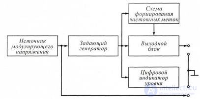
Figure 3.7 Simplified structural diagram of GKCH
3.3.3 Noise and Noise Generators
Widespread use in measuring equipment are noise signal generators.
Generators of noise signals (noise generators) produce fluctuation voltages with predetermined probabilistic characteristics. The main node of the noise generator is the master oscillator (Fig. 3.8). Its signals should have a uniform power spectral density over the entire required frequency band (theoretically, this is white noise ). In the master oscillator, physical phenomena are used, at which quite intense noises arise with static characteristics and parameters that are amenable to a fairly simple mathematical analysis.
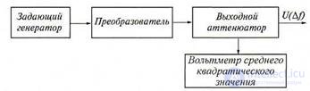
Figure 3.8 Block diagram of the noise generator
Heated wire resistor . As a model source of noise can serve as a heated wire resistor, the average square value of the voltage on which is calculated by the formula:
U2 = 4kTRΔf, (3.5)
where k = 1.38 · 10-23 J / deg - Boltzmann constant; T is the absolute temperature of the resistor in degrees Kelvin; R is the resistance of the resistor, Ohm; Δf - working band.
The resistor is in the form of a tungsten coil wound on a ceramic frame, the temperature of which is kept constant.
Bolometric noise generator . The bolometric generator also belongs to the sources of thermal noise power. The bolometer is a vacuum glass cylinder with a tungsten filament inside it.
Sources of thermal noise are used as exemplary noise voltage generators, since the calculated data are in good agreement with practical results. Photomultipliers, gas discharge tubes, noise diodes, etc. are also used in noise generators.
Gas discharge noise generators . Extensive use as a primary source of noise. In the centimeter wavelength range, gas-discharge noise tubes (GSHT) with a positive column were found.
Gas-discharge noise tubes have a high uniformity of the spectral power density of noise in a wide frequency band, a stable and relatively high power level, are easy to operate, resistant to harsh environmental influences and have a sufficiently high operational reliability.
The gas-discharge noise generator is made in the form of a glass tube filled with an inert gas (argon or neon). At one end of the tube is a directly heated, or heated cathode, on the opposite - an anode. The property of gas discharge tubes to generate noise due to the oscillations of electrons in the plasma. For the practical use of the noise radiation of the positive column of the HGT is placed in special generator sections. Depending on the frequency range and the type of tube, you can use the generator sections, made on the waveguide, coaxial or strip lines.
Waveguide noise generators are a segment of a waveguide, in the center of the wide wall of which at a small angle (7 ... 15) ° they place the HST. The inclined position of the tube in the waveguide ensures, when discharging, a uniform introduction of losses over a sufficient length of the line, thereby achieving a satisfactory matching of the CTG with the transmission line in a wide frequency range.
In the long wavelength part of centimeter waves, due to the difficulty of matching the tube with the transmission line, coaxial or strip noise generators are usually used.
In coaxial noise generators, the HGT is placed inside a tape helix, which is the internal conductor of the coaxial line. The outer conductor is the cylindrical surface of the line body. The shape of the helix (the gap between adjacent turns, the diameter of the helix) is determined based on the required characteristic impedance, the connection of the tube with the transmission line, the frequency range.
Strip noise generators are a symmetric strip line, along the axis of which is placed a gas-discharge noise tube.
The intensity of the radiation of the HMT is determined mainly by the electron temperature of the plasma. The losses made by the noise generator in the path, in the off state, are determined by the losses in the tube wall, transmission lines, etc.
In practice, noise generators in pulsed mode are used. The duration of the burning pulse of the HGT is limited by the duration of the transient process in the gas discharge. Depending on the permissible distortion, the minimum duration of the modulating pulse is 0.2 ... 1 ms.
Generators avalanche-span diodes . Of semiconductor noise generators in the practice of measuring widely used circuits on avalanche-transit diode (LPD). Generators consist of LPD and a generator section, matching the input resistance of the pn junction with the load resistance. The main source of noise radiation in the LPD are shot fluctuations of the saturation current of the diode. Noise generators on the LPD overlap the decimeter and centimeter wavelengths. They can operate both in the mode of continuous oscillations, and in the mode of pulse modulation with a pulse duration of several fractions of microseconds or more.
1. What physical phenomena can be used as the basis for creating noise generators?
2. What are the requirements for the waveform of a pulse generator?
3. Why use noise-like signal generators?
4. What serves as a model noise source?

Comments
To leave a comment
METROLOGY AND ELECTROradio-measurement
Terms: METROLOGY AND ELECTROradio-measurement