Lecture
Universal oscilloscopes use the method of measuring signal amplitudes using a scale grid placed on a CRT screen. The grid division price is set using an amplitude calibrator.
An illustration of this measurement method is shown in Fig. 4.5, where periodic signals are shown. The parameters of the pulses are determined as follows: Up = Su 1U; Up - span (pulse amplitude); "Su" - the price of dividing the grid vertically, V / div; T = C, Lx is the pulse repetition period; τп = Cx 1X - pulse duration; │С │ - the price of dividing the grid horizontally, c / div; ly, Lx, lx - expressed in grid divisions.
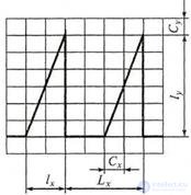
Figure 4.5 Definition of signal parameters using scale bar
The error of measuring the amplitude of the signal is not lower than 3 ... 5%. There are methods to improve the accuracy of measuring the amplitude of the signal under study, for example, compensation. These methods are most often used only in digital oscilloscopes, which allows obtaining numerical values of parameters with an accuracy of 1 ... 2%.
Unlike frequency meters and time interval meters, oscilloscopes can measure the parameters of signals of a complex time structure, such as stepped signals or code sequence signals. You can measure the parameters of random and transient processes. The simplest method of research is the method of calibrated sweep (calibrated tags) (Fig. 4.6).

Figure 4.6 Measuring time intervals using calibration marks:
voltage: uc - test; uk - calibration
The actual error of the method is about 10% and depends on the number of tags. Calibration marks of a known frequency are plotted on a signal image of duration τi by modulating the beam brightness, i.e. applying a voltage of known frequency f0 = 1 / T0 to the CRT grid. In this case, the duration of the signal is τi = nT0 , where n is the number of calibration marks.
Table 4.1 Interference Figures (Lissajous Figures)
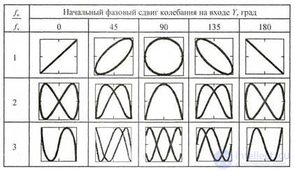
Let us dwell on the method of measuring the frequency of the interference figures, called Lissajous figures . The measurement is based on a comparison of the unknown frequency fx with the known frequency f0 reproduced by the measure. To this end, the oscillations of a known (exemplary) frequency f0 are fed to one oscilloscope input (for example, Y). The input X (with its own sweep of the oscilloscope disconnected) receives oscillations of the measured frequency fx. The frequency f0 of the model oscillator is adjusted so that the simplest stable figure is observed on the oscilloscope screen, the approximate views of which are shown in Table 1 at different phase shifts. 4.1. The shape of the Lissajous figures depends on the frequency ratio m / n and the initial phases of the compared oscillations.
The ratio of the frequencies of two harmonic oscillations can be defined as the ratio of the number of vertical points of intersection of Lissajous's figure m to the horizontal number of intersection points of n. For example, from fig. 4.7 it is easy to see that this ratio is:
fx = fo = m / n = 2/4 = 1/2. Hence, the measured frequency is defined as; fx = f0 / 2.
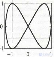
Figure 4.7. To determining the frequency ratio
The accuracy of this method for determining the frequency of the harmonic oscillation is quite high and is determined by the stability of the sample generator, however, obtaining and observing such figures is a rather complicated measurement task.
1. The basic requirements for the "unwrapping" voltage.
2. How does a sawtooth generator work?
3. List the main types of sweeps.
4. When do they use linear scanning? How to carry out a circular scan?
5. How to measure the amplitude of signals using an oscilloscope?
6. How to measure time intervals using a calibrated sweep and luminance marks?
7. How to measure the frequency of the signal using the Lissajous shape method?

Comments
To leave a comment
METROLOGY AND ELECTROradio-measurement
Terms: METROLOGY AND ELECTROradio-measurement