Lecture
2.6.1 Wideband level meters
Broadband level meters (DUT) differ from voltmeters in grading and input device requirements. In addition, due to the need to measure very low levels (up to –80 dB and less), DI amplifier stages always precede the detector level (Fig. 2.19).
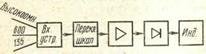
Figure 2.19 Diagram of a broadband level meter
IU graduation is usually performed in absolute voltage levels, when voltage is taken as zero
 U = 600⋅10−3 = 0.775 V eff. In the input device of the DUT, there is always an attenuator, which reduces the input voltage level to the input of the amplifying stages, usually by 10, 20, 30, 40 dB (or 1, 2, 3, 4, 5 Np) and therefore, it is possible to measure the voltage levels smaller than the usual extreme left-hand scale (-20 dB), for example: -12 dB on the scale and -40 dB on the attenuator correspond to the level of -52 dB.
The requirements for the input device of the DUT are due to the fact that in the communication technology there are two ways of switching on the DUT: 1) parallel to some resistance already present in the circuit (“parallel”) and 2) sequentially when the DUT itself (its input resistance) turns on “ the load, on which the level is measured. If in the first case, the DUT, in order not to change the operation mode of the circuit and not give a big error in determining the level that existed at some load before switching on the DUT, it must have the greatest possible resistance (the key controlling the input resistance should be in the “High-impedance” position) in the second case, the input resistance of the IC is made corresponding to the standard resistance for wired circuits: 600, 135, 75 Ohms. When installing the key controlling the input resistance to one of these values of the DUT, the “cut” turned out to be a practically matched load for the corresponding circuit. At the same time, the measured voltage level is equal to the power level at such a load, if the readout is based on the appropriate scale.
Often, the PS has two scales: one, graduated at absolute voltage levels, i.e., for the 600-ohm circuit (“0” corresponds to 0.775 V), the other for the 135-ohm (“0” corresponds to 0.367 V), or one for 135 ohm and the second for 75 ohm (“0” corresponds to 0.274 V).
It would be completely erroneous (although often encountered) when switching on “in parallel” to set the key controlling the input resistance to one of the low-impedance values (supposedly for “matching”). It is obvious that such a low-impedance input substantially shunts the already existing load resistances and a considerable systematic measurement error will occur.
The input device of the DUT used on air and symmetrical cable circuits usually contains a transformer that is symmetrical with respect to earth. For coaxial circuits, the input is asymmetrical, and (as in most electronic voltmeters), a wire connected to earth should be connected to the “Earth” terminal.
An example of a broadband level meter can serve as the IU-600.
2.6.2 The role of the input resistance of a voltmeter
The input resistance of a voltmeter is mainly determined by the resistance of the additional resistor, since the resistance of the frame of the measuring mechanism is small. But even this additional resistance cannot be very large, since its value is limited by the current that must flow through the measuring mechanism. In real voltmeters of a magnetoelectric system, the input resistance does not exceed several tens of kΩ. In a number of cases, such an input resistance is not enough for measurement in high-resistance radio engineering circuits, since this leads to a significant measurement error.
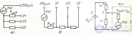
Figure 2.20 Figure 2.21
Consider the influence of the input resistance of a voltmeter on its readings when measured in high-resistance circuits.
The chain shown in fig. 2.21, consists of a voltage source E with an internal resistance equal to zero, and resistors R1 and R2. The voltage across the resistor R1 is measured by a voltmeter PV1 with an input resistance Rin .
In the absence of a voltmeter, a current flows in the circuit, creating a voltage drop of UR2 = ER2 / (R1 + R2). When a voltmeter is connected, the resistance of the BV portion decreases and becomes equal to R6b = R2RBX / (R2 - RBX)
The total resistance of the ABB circuit decreases, and the current from the source increases. This, in turn, leads to an increase in the voltage drop across the resistor R1 and, consequently, to a decrease in the voltage across the section of bw where the voltmeter is connected. The systematic error that occurs when a voltmeter is connected (the voltmeter shows not the voltage that was present before connecting it, but less) depends on the input resistance of the voltmeter and the resistance of resistors R1 and R2, that is, on the high resistance of the circuit. It is easy to make sure that with low resistance of the resistor R1, the error tends to zero for any input resistance of the voltmeter. For certain values of R1 and R2, other than zero, the error is the smaller, the greater the input resistance of the device.
So, for the circuit in question, the voltage on the section bv when connecting a voltmeter
U6b = ER6b / (R1 + R6e), (2.18)
i.e. differs from the original by
∆ U = U R 2 - Ubv = E  ( R 1 R +1 ( RR 22) (- R 1 R + bv ) R bv ), (2.19)
and the relative voltage change will be
∆ u 1
 δ u = UR 2 = 1+ R BX ( R 1+ R 2) / R 1 R 2). (2.20)
From the obtained expression it follows that when R1 → 0
 R BX ( R 1− R 2) the fraction R 1 R 2 → ∞, and the error δu → 0 . Similarly, when increasing the input resistance (RBX → ∞), the error is δu → 0 .
The desire to reduce the systematic measurement error led to the need to create a voltmeter with high input resistance.
1. What are the requirements for the input device of the level meter?
2. List the difference between a level meter and a voltmeter.
3. Describe how to turn on the level meter.
4. In what units is the signal level measured?
5. The role of the input resistance of a voltmeter

Comments
To leave a comment
METROLOGY AND ELECTROradio-measurement
Terms: METROLOGY AND ELECTROradio-measurement