Lecture
4.3.1 Dual Channel Oscilloscopes
Two-channel oscilloscopes have two identical vertical deviation channels (the input of the first is Y1, the second is Y2) and an electronic switch that can alternately feed the output signals of the channels to the same Y plates. Depending on the control of the electronic switch, you can implement the following main modes of operation oscilloscope; single channel (one signal is visible on the screen, applied to Y1 or Y2); alternately (both signals are visible on the screen by switching the electronic switch during each reverse sweep).
4.3.2 Dual Beam Oscilloscopes
Dual-beam oscilloscopes have two Y channels and a special two-beam CRT, in which there are two independent electron guns and a pair of deflection plate systems. The horizontal scanning of the rays is common and it starts from the scanning generator, and the vertical one starts from its own channel Y, which allows one to observe oscillograms of two signals on the screen (without their periodic interruption, as in two channels). Such oscilloscopes are much more complex circuitry and more expensive than dual-channel ones.
4.3.3 Storage Oscilloscopes
In the study of single pulses and periodic signals with high porosity, storage oscilloscopes are used, the basis of which are storage tubes.
The memory CRTs contain the same elements as the universal oscilloscope CRT, and are additionally equipped with a memory node and an image playback system. The memory node consists of two flat grid electrodes arranged parallel to the screen (Fig. 4.8). Directly at the screen there is a target covered with a dielectric layer. On top of the target is another electrode in the form of a grid with a larger structure - a collector.
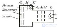
Figure 4.8. Memorizing CRT:
А'2, М ', К' - reproducing system
The image is recorded by a high energy electron beam.
(recording beam). The electrons of the beam are deposited on the target and the amount of charge is proportional to the current of the beam. As the beam moves on the target, a potential relief is created, which repeats the shape of the oscillogram. After the termination of the signal, the potential topography of the target persists for a long time. To observe the recorded image allows the reproducing system, consisting of a heated cathode K ', the anode A'2 and the modulator M'. The cathode of the tube creates a stream of low energy electrons, the density of which is regulated by a modulator M '. As a result, a broad defocused electron beam is formed, irradiating uniformly the target. The target potential is selected so that, in the absence of the recorded image, the slow electrons of the reproducing beam cannot pass through it. If there is a potential relief at these points of the target, a part of the electrons passes to the screen, causing it to glow. An oscillogram appears on the screen, repeating the shape of the potential topography of the target. They erase the recording by feeding a negative pulse to the collector, leveling the target potential.
In memory CRT there are three characteristic modes of operation:
• observation of the signal without recording the image; there is a small positive voltage Ucol = + 50 V on the collector, zero potential Uimish = 0 on the target and it is transparent to fast-moving electrons;
• recording mode; Ukol = + 50 V, the target is supplied with a positive potential Umish = 30 V, and the target becomes less transparent, therefore, rapidly flying electrons knock out secondary electrons and create a positive potential relief on the target that remains for a long time;
• play mode; the target potential again becomes zero Umish = 0, except for those places where the relief is recorded; The target is irradiated by a wide stream of slowly flying electrons from the reproducing system; for this stream, the target is transparent only at the terrain where the signal is recorded.
The latest models of memory CRTs have a recording speed of signals from 2.5 to 4000 km / s.
4.3.4 Dot Matrix Display Panel
A new display device used in modern oscilloscopes with analog-digital and fully digital conversion of the signal under study is the matrix display panel. It is a set of discrete emitters arranged in a certain way (liquid crystal, gas-discharge, solid-state, plasma, etc.). In fig. Figure 4.9 shows the design of the matrix gas discharge panel.
The matrix panel contains two glass plates 1 , on the outer surfaces of which thin conductive strips are deposited - the anodes 2 and the cathodes 3. The anodes are placed on the face plate through which the light passes, therefore they are made transparent.
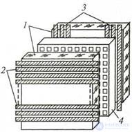
Figure 4.9 Matrix Panel:
1 - glass plates; 2 - anodes; 3 - cathodes; 4 - matrix
Between the plates are placed a dielectric matrix 4 with holes that form the gas-discharge (or other) cells at the points of intersection of the electrodes. The panel is filled with a helium-neon mixture and sealed. The image of the signal being studied is reproduced by alternating luminescence of gas-discharge cells. For this purpose, from the control circuit of the panel, the positive and negative voltage pulses of the ignition are supplied to the anodes and the cathodes of the plates. The number of the anode to which the ignition voltage pulse is applied determines the scan line, and the cathode number the column; on their crosshairs is a glowing cell panel. This principle of beam sweep control is called matrix , in practice it is implemented by digital methods and devices.
The advantages of the matrix display panels: small size and weight, low supply voltage; there are no geometric distortions, the luminous point is stable. Developed panels with internal memory that can not only play, but also remember the signal image. The digital control principle allows you to simply combine the signal image with the alphanumeric display of its parameters on a single screen. The disadvantages of the matrix display panels include the complexity of the control circuit, the relatively low resolution and low speed.
4.3.5 Speed and Strobe Oscilloscopes
When observing and studying short pulses (signals of nanosecond duration) and microwave oscillations, a number of difficulties arise that make the use of universal oscilloscopes difficult. There are several main factors that make it difficult to use universal oscilloscopes for this purpose:
• the effect of the capacity of CRT plates on the steepness of the front of the signal under study;
• parasitic resonances that occur in the circuits formed by the capacitance of the plates and the inductance of the lead wires, including the inputs
plates;
• the influence of the finite time of flight of electrons between the plates of a CRT, amounting to 1 ... 10 ns;
• it is necessary to have a wide bandwidth of the channel Y; the bandwidth for transmitting a rectangular pulse can be approximately calculated using the formula Δf ≈ 2.5 / τi, then for a pulse duration τи = 1 ns, the bandwidth Δf ≈ 2.5 GHz;
• to observe nanosecond pulses and microwave oscillations, high beam velocities are required on the screen; for example, to obtain an image of a pulse with a duration of τi = 5 ns on a CRT screen of width L = 100 mm, the speed of the beam should be of the order of v = 20 000 km / s (v = L / τi - the speed of the beam, L - the size of the image on screen).
All noted shortcomings are required to be considered when developing high-speed oscillographs. In high-speed oscilloscopes operating in real time, special traveling-wave CRTs are used, which as a result does not allow obtaining a high sensitivity of the vertical deflection channel (Sу ≈ 1 mm / V). Creating high-speed reamers also encounters difficulties; it is necessary to raise the voltage sweep to a few hundred volts. The developed high-speed oscilloscopes have an upper cut-off frequency of 5 ... 7.5 GHz. In the study of fast processes with a low voltage amplitude, the described high-speed oscilloscopes are not suitable due to low sensitivity. The problem is solved with the help of a special stroboscopic attachment to the universal oscilloscope. The stroboscopic oscillography method makes it possible to significantly reduce the scanning speed compared to that required for direct observation of the signal under study on a high-speed oscilloscope. Stroboscopic oscilloscopes make it possible to observe very short periodic pulses and high-frequency signals up to microwave oscillations.
A stroboscopic oscilloscope is called in which in order to receive on the screen of a CRT a waveform use the selection of its instantaneous values (signal sampling) and perform a temporary transformation, i.e. image signal give an enlarged time scale. The principle of operation consists in converting several identical short-duration signals into one having a longer duration and repeating the shape of the input signals. Sweep speed is reduced by transforming the time scale. An image appears on the oscilloscope screen in a form similar to the signal under study, but on a larger time scale. The block diagram of the stroboscopic oscilloscope, in addition to the nodes typical for universal oscilloscopes, contains a stroboscopic converter and a stroboscopic sweep device, including a sweep generator, a strobe pulse generator, and an automatic shift unit specifying the read step.
The main device of the oscilloscope is a stroboscopic converter, in which the Duplicate signal under investigation is sampled using short-duration strobe pulses. The block diagram and timing diagrams of the input signal converter are shown in fig.
4.10. The pursued pulses Uc, duration τ and repetition period Tc are served together with the strobe pulses U2 to the stroboscopic mixer (Fig. 4.10, a). The repetition period of strobe pulses Tstr = Tc + Δt, where Δt is the read step . The duration Δt is chosen from the condition Δt = τ / n (n is an integer). As a result of this transformation, it turns out that the first strobe pulse coincides with the beginning of the first pulse Uc (1), the 2nd one is shifted from the beginning of the 2nd (2) pulse Uc by Δt, the 3rd one is shifted from the beginning of the 3rd (3rd ) pulse Uc by 2Δt, etc. (rice, 4.10, b).
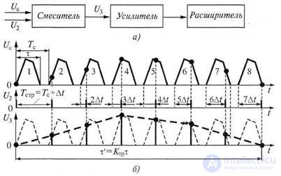
Figure 4.10 The principle of operation of the stroboscopic converter: a - diagram; b - time diagrams
At the output of the mixer, short pulses of U3 appear (bold lines with a dot), coinciding in time with the strobe pulses (U2), but having an amplitude equal to the amplitude of the Uc pulses under study at the time of arrival of the strobe pulses U2. Therefore, the U3 pulses are called strobe pulses modulated in amplitude by the Uc signal under study (Fig. 4.10, b). As can be seen from the diagram of the signal U3, the envelope of the modulated strobe
pulses (bold dashed line in Fig. 4.10, b) almost repeats the shape of the studied pulses Uc, but in comparison with them is stretched in time. The C pulses are amplified, then expanded to the required duration and fed through the Y channel amplifier to the deflection plates of the stroboscopic oscilloscope. At the same time, on the oscilloscope screen with conventional CRT and sawtooth scan, the pulse shape Uc is observed.
For greater image contrast, the flat areas of the extended signal under study are illuminated with pulses of the beam illumination circuit. Thus, the image of the signal will have the appearance of glowing dashes, which is a characteristic feature of the oscillogram of the stroboscopic oscilloscope.
The degree of stretching of the observed pulse in time (temporary transformation) is characterized by the time scale transformation ratio Ktr = nTstr / τ, where n is the number of strobe pulses that read the pulse Uc. Since n = τ / Δt, then:
Ctr = Tr / Δt, (4.2)
In modern oscilloscopes, the Ktr reaches tens of thousands, which makes it possible to observe the shape of nanosecond pulses during normal sweeps. The bandwidth of modern stroboscopic oscilloscopes exceeds 10 GHz; input level - from a few millivolts to tens of volts; measurement error 5 ... 7.5%.
4.3.6 Digital Oscilloscopes
A digital oscilloscope allows you to simultaneously monitor the signal on the screen and obtain the numerical values of a number of its parameters with greater accuracy than is possible by reading quantitative values directly from the screen of a conventional oscilloscope. This is possible because the signal parameters are measured directly at the input of a digital oscilloscope, whereas the signal that passes through the vertical deviation channel can be measured with significant errors (up to 10%).
On the screen of a modern digital oscilloscope, besides the oscillograms themselves, the state of the controls is displayed.
(sensitivity, sweep duration, etc.). Provides information output from the oscilloscope to print and other functionality. However, this does not limit the capabilities of digital oscilloscopes. Pairing digital oscilloscopes with microprocessors allows you to determine the effective value of the signal voltage and even calculate and display on the screen Fourier transforms for any kind of signal. Digital oscilloscopes perform full digital signal processing, so they usually use the display on the latest display panels.
In digital oscilloscopes, the measurement result is displayed in three ways:
• in parallel with the observation of the image of the signal on the screen, its numerical parameters are displayed on the board;
• the operator brings the light marks to the image of the signal on the screen so as to mark the parameter being measured, and by the number on the corresponding adjustment determines the value of the parameter of interest;
• use special indicators and a raster method of imaging the studied signals and digital information.
In modern digital oscilloscopes automatically set the optimal image size on the screen of the tube. Below are the parameters of a modern digital automated oscilloscope, which is a characteristic representative of this class of devices.
The block diagram of a digital oscilloscope contains: input attenuator; amplifiers for vertical and horizontal deflection; amplitude and time interval meters signal interfaces and meters; microprocessor controller; sweep generator; synchronization circuit and electron beam tube.
Technical characteristics of a typical modern digital oscilloscope:
• bandwidth 0 ... 100 MHz;
• screen size 80 x 100 mm;
• error of digital measurements 2 ... 3%.
Functionality: automatic image sizing; automatic synchronization; difference measurements between two labels; automatic measurement of the amplitude, maximum and minimum of the amplitude of the signals, period, duration, pause, front and fall of the pulses; entrance to the public channel.
From the block diagram presented in fig. 4.11, it is seen that the amplitude and time parameters of the signal under study; determined using the built-in instrument gauges. Based on the measurement data, the microprocessor controller calculates the required deflection and sweep factors and, through the interface, sets these coefficients in the hardware of the vertical and horizontal deflection channels. This ensures that the image remains unchanged vertically and horizontally, as well as automatically synchronizes the signal. The microprocessor controller also polls the position of the controls on the front panel, and the polling data after encoding is sent back to the controller,
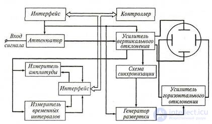
Figure 4.11 Simplified block diagram of a digital oscilloscope
which includes the corresponding automatic measurement mode through the interface. The measurement results are displayed on a separate light panel (it can be embedded in the tube screen), with the amplitude and time parameters of the signal being displayed simultaneously.
1. The principle of operation, parameters and basic modes of operation of the storage oscilloscope.
2. What are the features of nanosecond pulse oscillography?
3. What is the principle of stroboscopic oscillography of fast processes?
4. What are the requirements for an oscilloscope when measuring pulsed signals?
5. Explain the principle of building digital oscilloscopes.
6. What are the main components of a digital oscilloscope?
7. Name the main parameters and characteristics of a modern digital oscilloscope.

Comments
To leave a comment
METROLOGY AND ELECTROradio-measurement
Terms: METROLOGY AND ELECTROradio-measurement