Lecture
An important and difficult-to-achieve characteristic of the paths and communication channels is the level of the extraneous voltages arising from them or penetrating from the outside.
The difference between the measuring level of the useful signal (p) and the level of interference (pn) is called noise immunity:
An = p - rp, (6.15)
The required quality of information transmission should ensure, with simultaneous exposure to interference of all kinds (except emergency) in the channels of the greatest length with the most unfavorable combination of influencing factors - all noise.
In standard telephone channels there are: a) self-noise consisting of thermal noise resistances and noise of electronic tubes and transistors working in the channel; b) noise of non-linear transitions due to the nonlinearity of the amplitude characteristics of the channel devices (group and intermediate amplifiers; in air circuits, filters containing cores made of magnetic materials, modulators, etc.); noise of linear transitions arising due to transient currents from adjacent parallel circuits.
In addition, channel noise can appear from power sources and all kinds of external interference (from radio stations, high voltage lines, electrified railways, atmospheric phenomena). All the noise, adding, creates at the end of the channel a general noise that interferes with the normal perception of the signal.
Norms, as a rule, take into account noise immunity in the worst conditions, measurements are usually carried out in conditions other than the worst case. Therefore, it is very important to pre-calculate the expected value of the measured value for specific measurement conditions, taking into account the structure and characteristics of the object being measured.
The data obtained as a result of measurements may meet the standards, but not coincide with the expected ones. Then there is no guarantee that under the worst conditions the norms will be sustained. The reasons for this discrepancy must be clarified.
The disturbing effect of noise depends on: 1) the ratio of its power to the power of the useful signal; 2) the frequency composition of the noise.
The power of the intrinsic and non-linear noise is related to the transmission level When the transmission level decreases, the relative level of intrinsic noise increases, and the level of nonlinear noise decreases. With an increase in the transmission level, on the contrary, the noise is nonlinear, and the relative noise level falls. The linear noise power does not depend on the transmission level of this circuit, their level increases with increasing number of amplifying sections N.
The frequency composition of the noise is important because the voltages of different frequencies acting on the telephone or loudspeaker are not equally perceived by the human ear. In fig. 6.15 shows the curves of the approximate dependence of the perception by the human ear of the same power level of different frequencies through the telephone (Fig. 6.15a) and through the speaker (Fig. 6.15 b).

Figure 6.15. General view of the perception curves of the human ear
the same level of different frequencies using: a) a telephone; b) dynamic loudspeaker
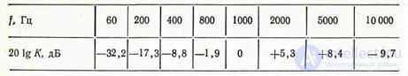
For the ear-speaker system, the maximum sensitivity is detected in the frequency range of 2000-5000 Hz, the sensitivity at 1 kHz is taken as a unit. For the ear system, the phone sensitivity, close to the maximum and taken as a unit, takes place at a frequency of 800 Hz. For other frequencies, the International Advisory Committee for Telegraphy and Telephony (CCITT) on the basis of numerous experiments established the appropriate "weighted", or, as they are called, "psophometric" coefficients (in Greek, "psofos" - noise).
In tab. 6.1 shows these coefficients in decibels (201g / K) for the telephone-ear system and in the table. 6.2 - for the ear-speaker system. In this regard, the concept of psophometric power and psophometric noise voltage (or interference) was introduced.
Table 6.1

Table 6.2
Psophometric voltage Ups (or Uφ) is the interference voltage that exists at a terminal resistance of 600 ohms (switched on consistently at the output of the circuit or through a transformer) and is measured taking into account the unequal influence of voltages of various frequencies on the quality of telephone (or broadcasting) reception.
Psophometric voltage for telephone transmission is Ups = √ ∑ (KfUf) 2, (6.16)
where Uf - effective values of the individual components of the interference voltage with a frequency f; Kf - psophometric (weight) coefficient for the same frequency f. The weighting factor for the frequency of 800 Hz is here assumed to be equal to one.
Thus, Upc is equal to the rms (effective) value of the voltage frequency of 800 Hz, which will produce the same disturbing effect on the receiver as the total interference voltage in the circuit. For a standard telephone channel with a width of 300 to 3400 Hz, the psophometric voltage Uпc with a uniform distribution of noise in this spectrum (three so-called “smooth interference”) can be calculated by the formula
Ups = Ud / 1,33 = 0,75Ud, (6.17)
where 1.33 is the average psophometric coefficient for a given
frequency bands. Accordingly, the power Pps = 0,752Rd = 0,56Rd.
According to CCITT requirements:
1) the average value of the psophometric noise power in the channel of the PM reference cable communication line (2500 km long), measured at a point with zero relative level, should be no more than PcL = 10,000 pW per hour of maximum load;
2) the average value of psophometric noise power in the HF channel of an air reference line with a length of 2500 km at a point of zero relative level should be no more than Pf = 20,000 pW per hour of maximum load. The voltages corresponding to these powers and measured at the terminals of the long-distance switch of the receiving station (at the point with a relative level of 7 dB) are equal: for the cable line Ush.k = 1.1 mV psof; for the overhead line Ush.v = 1.55 mV psof (see task 125).
The average psophometric power of the noise generated by terminal equipment and re-reception equipment for the reference circuit is taken as 2500 pW. Since the noise power is proportional to the number of amplification sections that can be considered to be located approximately evenly, then for a highway L of length, the norm for the permissible noise power at a point with a relative zero level is:
for the cable chain Ps.
Depending on the climatic conditions, CCITT recommendations are implemented differently. In the USSR, for air circuits made from non-ferrous metals with a maximum length of the retransfer section of 2000 km for a point with a relative level of 7 dB, the following standards are adopted for psophometric voltage of all types of noise (Ush.v) depending on weather conditions: for dry weather in winter and summer 1 , 25 mV; for conditions “summer-damp” 1.4 mV; with frost up to 5 mm 2.8 mV for the B-12 and B-12-2 equipment and 1.6 mV for the B-3 and B-3-2 equipment; when frost exceeds 5 mm, the norm increases to 7.4 and 6.1 mV, respectively.
For other lengths of the received section L, the value of the permissible noise voltage Uml is found from the formula
Uml = Uш.к (в) √l / lmax, (6.18)
where Imax for air chains from non-ferrous metals is 2000 km and Imax for cable chains is 2500 km. It should be borne in mind that when receiving channels into operation, the norms for noise are tougher, since the data given above correspond to the hour of greatest load, which cannot be obtained during the reception.
To measure psophometric voltages, devices called psophometers or interference voltage indicators are used. In fig. 6.14 is a diagram of a widespread pointer.

Figure 6.14 Scheme of the interference voltage indicator (psofometer) type
UNP - 60
voltage noise type UNP - 60. The input device of the device consists of a transformer symmetric with respect to the earth with a voltage divider in its output winding. The input resistance of the transformer is not less than 8 kΩ, but by connecting the corresponding shunt to the primary winding, it can be made equal to 600 ohms with an error not exceeding 5%. To measure the interference voltage on the lines through which the direct current flows (the GTS circuits), the device provides for the possibility of connecting to the measured object through isolating capacitors (not shown). Key K can be set to three modes of operation:
1) the device operates as a quadratic voltmeter (without filter) with measurement limits from 0.1 mV to 10 V (-80 ÷ + 20 dB) with a basic error of ± 5% in the frequency range of 30 - 20000 Hz;
2) the device operates with an F1 filter for measuring psophometric voltages in the PM channel;
3) the device works with filter F2 for measuring psophometric voltages in broadcasting channels.
The amplifier is made with deep negative feedback, which ensures the stability of the instrument. The total gain is 60000 (96 dB). The detector is quadratic, constructed by the piecewise linear approximation method. In the range from 50 to 20,000 Hz, the frequency response of the gain (without filters) is flat. The amplitude characteristic within the limits of measurements is linear up to 25 V at the input. The frequency characteristics of the filters meet the requirements of CCITT
1951
The device has a calibration device to check the operation of the device before measurements. It contains a generator of sinusoidal voltage of 800 Hz. In the “Calibration” position, the instrument readings in the voltmeter mode and when the F1 is turned on should not differ from each other by more than 5%. The device can be powered from AC power or from a 24 V DC source.

Comments
To leave a comment
METROLOGY AND ELECTROradio-measurement
Terms: METROLOGY AND ELECTROradio-measurement