Lecture
General information . Devices in which the measurement process occurs automatically , without the participation of operators , are called automatic measuring devices ( AIP ). They are designed to measure and record the parameters characterizing the technological processes of production . Such parameters include: temperature , pressure , liquid level and flow rate , concentration and composition of gases and liquids , electrical voltages and currents , power , frequency , etc.
The current widespread use of AIPs and the increasing need for them are explained by a number of the most important metrological and operational characteristics: high accuracy (error up to 0.001%) and sensitivity (up to 10–8), slight dependence of instrument readings on operating conditions , low energy consumption , the possibility of using low-power primary signal converters , the possibility of simultaneously measuring several quantities , obtaining documentary information .
These indicators are provided by the use of a compensation measurement method , the use of sophisticated electronic devices characterized by low inertia and high output power, some complication of the AIP node circuits, the use of an objective reading of the measured parameters.
In the general case, the block diagram of the AIP of continuous action can be represented as (Fig. 13.3). Here PP is the primary converter , IC - measuring circuit , U - amplifier , RD - reversible motor , P - gearbox , KU - correction device , WU - output device . The links of the direct signal transmission or the direct path of the system (IC, U, RD, R), covered by the correction device KU, form a tracking system CC and provide automation of the measurement process.
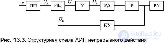
The principle of operation of the tracking system consists in comparing the measured Ux value , coming from the primary converter PP, with its compensation value U K , produced by the correction device KU. The difference of these values ∆ U = U 1 is amplified and fed to the reversible motor RD, which, acting through the reducer P on the correction device KU, at the same time ensures the operation of the output device VU. The system equilibrium occurs when ∆U = 0. This equilibrium is possible in an astatic system , a necessary condition of which is the presence of an integrating link in the direct signal transmission path. In this case, the integrating link is the reversible motor RD, since the speed of rotation of its output shaft is proportional to the voltage applied to the control winding:
dα / d t = kU 2 , or α = k ∫ U 2d t ,
where α is the angle of rotation of the output shaft of the reversing engine; k is a constant coefficient ; U 2 is the output voltage of the amplifier .
In fact, at equilibrium, ∆U ≠ 0, and is determined by the sensitivity threshold ∆ U of pores - the minimum value of ∆ U , which leads to the engine start-up, and the inertia of the system links.
According to the type of measuring systems, existing continuous-action AIPs are subdivided into balances by one parameter, DC potentiometers, and instruments with a differential transformer system . The principles of construction and requirements for the measuring circuit and the correction device of the listed AIPs have significant differences.
Automatic bridge to measure temperature . A simplified block diagram of an automatic balanced bridge designed to measure temperature using an Rt thermistor is shown in (Fig. 13.4). A thermistor connected to one of the shoulders of the bridge is connected by means of a communication line with resistance R l . The three remaining arms are made of thermostable resistors R , R 2, R 3, R 4.
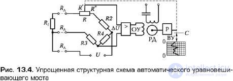
Balancing the bridge at the initial temperature is carried out by changing the position of the variable resistor R. If the temperature deviates from the initial, the resistance of the thermistor changes and the bridge goes out of balance . The error signal ∆ U appears at the input of the amplifier. The amplified signal is fed to the control winding of an op-amp of a reversible motor RD, on the shaft of which there is a gearbox P mechanically connected with the engine of the variable resistor R and the pointer of the output device of the control unit. Through these connections, the bridge is automatically balanced.
The test of the error signal occurs as long as ∆ U is greater than the sensitivity threshold of the regulator ∆ U then . The output value can be counted on a scale calibrated directly in degrees Celsius. The graduation of the scale is valid for each specific thermistor.
The three-wire connection of the thermistor can significantly reduce the influence of the connecting wires R l on the measurement accuracy. Indeed, taking into account the fact that two wires with resistance R l are connected to the adjacent shoulders of the bridge, and the third with the same resistance to the diagonal of the power bridge, we get:
(  + R l ) R 4 =
  ( R 3 + R L ),
Where = Rt + R ' and = R2 + R " .
When the symmetry of the shoulders of the bridge, i.e. at = R 4 . we get a complete elimination of the influence of R on the measurement error . The instrument scale, i.e. the dependence α = f ( T ), has a linear character when the thermistor R is turned on, in the shoulder of the bridge circuit adjacent to the relay R.
Automatic DC potentiometer . As an example of the implementation of an automatic device using a compensation measurement method, let us consider a potentiometer working in conjunction with a thermocouple, at the ends of which a thermo-emf is generated E 1 (Fig. 13.5).
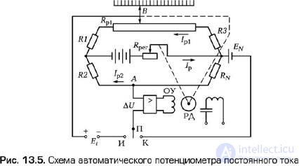
The compensating device of this potentiometer is made by a bridge circuit. The measurement process is carried out in two steps. When the position of the switch P is setting the operating current using a normal element with EMF EN . The voltage unbalance ∆ U = EN - RNI p2 is fed to the input of the amplifier. From the output of the amplifier, the voltage is applied to the control winding of an op-amp of a reversible motor RD, which changes the position of the rheostat slider R reg . The device automatically brings the value of ∆ U to zero. In this case, certain currents I p , I p1 , I p2 are installed in the circuit.
When the position And the switch P is switching the mechanical connection of the taxiway on the engine B potentiometer. Measured EMF E 1 thermocouple is balanced by a compensating voltage
Uk = ( R p1 + R 1 ) I p1 - R 2 I p2 ,
by the influence of the voltage unbalance ∆ U on the reversible motor RD, mechanically connected with the slider B of the potentiometer, the position of which affects the resistance R p1 of the compensating resistor. The value of measured thermo-emf Et is read according to the position of the slider B on a scale calibrated in volts.
Modern automatic potentiometers for temperature measurement are supplied with stabilized power sources. They do not have the normal element and the mode of automatic installation of operating currents.
Differential - transformer device . The circuit shown in (Fig. 13.6) has found wide use for measuring pressure (automatic pressure gauge), fluid level (level gauge) and fluid flow (flow meter).
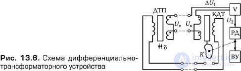
The main nodes of the measuring circuit are the differential transformer converter ( DTP ) and the compensation differential transformer ( CTD ). On the device, these devices are similar. Their secondary windings are connected in series and counter. The movable core of the accident has the ability under the influence of any mechanical quantity to move along the axis of the coils at a distance δ . At the output of the accident, a signal Ux = k δ arises, and the QDT forms a compensating voltage U к . If Ux ≠ U к , then the system performs the signal ∆ U 1 = Ux - U k until ∆ U 1 becomes equal to ∆ U then . The angle of rotation of the output shaft of the reverse motor XR is functionally related to the value of Ux and displays this value. Since Ux = F ( δ ), the equation of the scale of the entire device is represented as α = f ( δ ).

Comments
To leave a comment
METROLOGY AND ELECTROradio-measurement
Terms: METROLOGY AND ELECTROradio-measurement