Lecture
The devices described above do not solve many problems that arise when measuring different values of alternating current: electromagnetic and electrodynamic - low-frequency, electrostatic has a low sensitivity.
The use of a magnetoelectric mechanism in combination with an AC-DC converter allows one to significantly expand the possibilities of measurements on an alternating current.
According to the type of converter, these devices are divided into: rectifying and thermoelectric (see Table 2.2.).
Rectifiers consist of a semiconductor AC / DC diode converter.
Due to the nonlinearity of the current-voltage characteristics of the diode, the spectrum of the current flowing through it contains frequency components that are multiples of the frequency of the measured voltage, as well as a constant component reflecting information about the value of the measured value.
It is technically more convenient to isolate the DC component of the output current (or voltage), if its value is associated with a certain functional dependence with the measured voltage, and which can serve as a signal of measurement information.
In this case, the main operations performed by the electrical circuit of a voltmeter: the conversion of the measured voltage using a nonlinear device, the selection of the DC component and its measurement with an indicating measuring instrument.
Table 2.2 Magnetoelectric system with converters
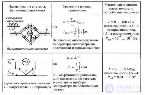
The converter circuit can be built in different ways, but as a result, a unipolar pulsating current (full-wave or half-wave) must flow through the measuring mechanism.
In tab. 2.2 shows the simplest full-wave (two-stroke) diode rectifier.
Due to the fact that the magnetoelectric measuring system responds to direct current, the instrument readings will be proportional to the average rectified value of alternating current or voltage.
This circumstance is very significant, since the instruments are often calibrated in the mean square values of the sinusoidal current.
This means that the scale of the instrument represents not the value to which the instrument reacts (that is, the mean straight), but the value multiplied by Kf = 1.11.
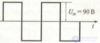
Figure 2.2 voltage meander form
When measuring the parameters of an alternating non-harmonic signal, a methodical error almost always occurs. For example, when calibrating a measuring device on a sinusoidal current, a 100V voltage point corresponded to a 100V scale point. If this measuring instrument is supplied with a voltage that has the form of a meander with the parameters shown in Fig.2.2 (recall that for such a signal Ka = Kf = 1, that is, Um = U = Uav in ≈ 90 V), then its readings will also be about 100 V (1.11 U avp) and the absolute error will be: Δ = 100 - 90 = 10 V.
Rectifier devices are used as combined meters of direct and alternating current and voltage with current measurement limits from 1 mA to 600 A, voltages - from 0.1 to 600 V.
The advantages of rectifying devices are high sensitivity, low self-consumption of energy and the ability to measure in a wide frequency range. The frequency range of the rectifier devices is determined by the diodes used. Thus, the use of point-like silicon diodes provides measurement of alternating currents and voltages at frequencies of 50 ... 105 Hz. Rectifier devices are in the form of multi-range and multi-purpose laboratory measuring devices. This type of measuring instrument refers to the so-called tester .
Devices of a thermoelectric system consist of a thermoelectric converter (more simply, a thermal converter) and a magnetoelectric microammeter. The thermal converter contains a heater with measured current flowing through it, and a thermocouple, at the ends of which thermoEMF occurs. A microammeter is included in the thermocouple circuit for measuring the thermal current. The thermocouple work junction is in thermal contact with the heater, which is a thin metal alloy wire with high resistivity (nichrome, manganin). Even thinner wires from thermoelectrode materials are used for the manufacture of thermocouples. With the passage of the measured current through the heater, the place of its contact with the thermocouple heats up to the desired temperature, and the cold junction remains at ambient temperature. The operation of the device is based on the thermal effect of current, and therefore a magnetoelectric device with a thermoelectric converter measures the mean square value of alternating current of any shape.
Thermoelectric devices are mainly used to measure currents. They practically do not use voltmeters, since their input resistance is extremely small. The advantage of thermoelectric devices is a wide frequency range (up to 10 MHz). Disadvantages:
low sensitivity, low accuracy class (1.5 ... 4.0).
2.2.2 DC compensators
The most accurate measurements can be made by comparing with a measure. Devices in which the measurement is made by comparing the measured value with the reference, called compensators. The principle of operation of the compensator is based on balancing (compensation) of the measured voltage by the known voltage drop across the reference resistor. The moment of full compensation is fixed by a null indicator (NO), which reacts to very small constant currents. AC and DC compensators have been developed.
A simplified diagram of a DC compensator for measuring the voltage Ux is shown in Fig. 2.3. A constant voltage source Eozdozdaet operating current Ip in the circuit, consisting of a series-connected measuring RI, the installation (reference) Ry and adjusting REFressers. As a source of exemplary EMF (EMF measure), a normal element ENE is used - a galvanic cell manufactured using a special technology, the average value of which is at a temperature of 20 ° C is equal to 1.08686. The installation resistor Ry is a special-purpose resistance coil known and stable resistance.
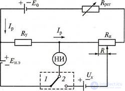
Figure 2.3 Simplified DC compensator circuit
Using the switch, the zero indicator is first included in the set-up resistance circuit Ry (switch position 1) . When this adjustment resistance R reg achieve the absence of current in the circuit of the null indicator. This means that I p R y = En.e, from which the value of the operating current is defined as Ip = En.e / Rу = 10 -n A (for each type of compensator, n is an individual and constant number, which is ensured by the constant voltage source parameters EN and installation resistance R y) . Then the null indicator is switched on in the measuring circuit (switch position 2) and by changing the measuring resistance R and achieving zero current, and therefore, the equality Ux = IpR = Eн.e R / Rу. So, the measured voltage is determined with sufficiently high accuracy and without disrupting the operation of the measuring circuit, since at the time of measurement the current does not flow through the indicator.
With the help of a compensator, it is also possible to determine the current in the device under study, converting it in advance into a voltage according to the formula IX = Ux / R0, where Ra is some model design resistance.
When measuring voltages in production, automatic compensators are used, in which the difference value ∆UX = IpRnac - IpRcon -> 0 is maintained using a tracking system (Rnach and Rcon parts of measuring resistance Ri at the beginning and end of the tracking cycle).
The error of the compensator is determined by the errors of the resistors RI, Rr EMF of the normal element ENE, as well as the sensitivity of the null indicator. Modern DC potentiometers have an accuracy class from 0.0005 to 0.2. The upper limit of measurement is 1 ... 2.5 V. The lower limit of measurement may be units of nanovolts.
1. Explain the work of the full-wave straightening scheme.
2. What are the advantages of the compensation measurement method?
3. Explain the operation of the device thermoelectric system.
4. How to translate the average rectified voltage value into the rms value?

Comments
To leave a comment
METROLOGY AND ELECTROradio-measurement
Terms: METROLOGY AND ELECTROradio-measurement