Lecture
When measuring the voltage using the direct assessment method, a voltmeter is connected in parallel to a section of the circuit under study. To reduce the methodological measurement error, the own consumption of the voltmeter should be small, and its input resistance should be large. Therefore, in recent years, electronic voltmeters are mainly used.
Electronic voltmeters are a combination of an electronic transducer and a measuring device. In contrast to the voltmeters of the electromechanical group, the electronic voltmeters of constant and alternating currents have high input resistance and sensitivity, wide measuring limits and frequency range (from 20 Hz to 1000 MHz), low current consumption from the measuring circuit.
Electronic voltmeters are classified according to a number of features:
• by purpose - voltmeters of direct, alternating and pulsed voltages; universal; phase sensitive; selective;
• by measurement method - devices of direct assessment and comparison devices;
• according to the nature of the measured voltage value - amplitude (peak), mean square value, mean-rectified value;
• over the frequency range - low-frequency, high-frequency, microwave.
In addition, all electronic devices can be divided into two large groups: analog electronic with a needle reading and discrete-type devices with a digital reading.
When measuring the current with an electronic voltmeter, the current is first converted into voltage, and then determined by the formula: Ix = Ux / R0, where Ro is the model design resistance.
To measure the voltage, it is necessary to choose the device correctly, taking into account its measurement range, frequency range, accuracy class, power consumption from the measuring circuit, and the effect of the waveform on the measurement result. These parameters are specified in the technical documentation for the device. It should pay attention to the following important circumstances.
When measuring harmonic voltages, the frequency of the measured signal should be within the operating frequency range. It is necessary to check on the passport, whether there is an additional frequency error in the measured point.
When measuring signals of complex shape, the frequency range is chosen taking into account higher harmonics. If an electronic device with an amplitude detector is used, then its indications can determine the mean square value of U only for the case when the amplitude coefficient of the measured signal is known.
Similarly, when measuring with a device with a converter of the mean-rectified value Upr, to determine the mean square value of a signal, it is necessary to know the coefficient of its form Kf.sig. Then, taking into account formula (3.6), we get:
 U
U  To f . whitefish
, (2.3)
It must be remembered that the devices of medium-straight value are sometimes not at all suitable for measuring signals of complex shape, since they do not provide the necessary working frequency range.
When measuring on alternating current with the help of electronic devices, it should be borne in mind that their main mass has a “closed input” for the DC component of the signal.
This allows measurements to be made in circuits where the signal level is much less than the constant voltages of the rest mode of the circuit. However, when measuring pulse signals with amplitude transducers, special attention should be paid to this.
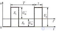
Figure 2.4 Diagrams for a voltmeter with an amplitude converter
In the time diagrams presented in fig. 2.4, it is shown how to determine the parameters of unipolar rectangular pulses, the amplitude Up, duration τ and frequency = 1 / T of which are known.
Let the scale of the measuring device be calibrated in the mean square values of the sinusoid. Then the instrument reading with the amplitude converter of the measured voltage should be Unp = Um / I 1.41. Due to the fact that the device responds only to the variable component of the signal presented in Fig. 2.4 relative to the time axis t ', the instrument readings will be: Upr = U + m / 1.41 or Upr = Um / 1.41 depending on the polarity of its connection, where U + = UP (T-τ) / T = positive amplitude value; U = Up τ / T is the negative peak value of the pulse.
Formulas for voltage conversion are obtained from the condition of equality to zero of the constant component, i.e. the squares S] and S2 with respect to the time axis t 'are equal:
S1 = U + mτ S2 = Um (T-τ), (2.4)
2.3.3 Features of current measurement
There are a number of methods for measuring the current in electrical circuits:
In addition to direct measurements, indirect measurements are widely used.
Direct current measurement. In this case, the ammeter is connected in series to an open circuit in which the current is measured (Fig. 2.5, a). The inclusion of an ammeter into the circuit under study distorts the measurement result. In particular, the presence in the scheme of fig. 2.5, and an ammeter with internal resistance RA leads to the fact that instead of the current Ix = UIR, which flowed in this circuit without an ammeter, after it is turned on, a current flows:
I 1 = R + U R A , (2.5)
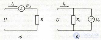
Figure 2.5 Current measurement circuit:
and - with the ammeter; b - using a voltmeter.
The absolute measurement error ΔI = Ix - I1 will be the greater, the higher the internal resistance of the ammeter RA .
Current measurement by indirect method using electronic voltmeters. Since there is a linear connection between voltage and rock in an electrical circuit (according to Ohm’s law), the current can be measured indirectly using the circuit shown in fig. 3.17, b. In this case, having measured the voltage across the resistance of the reference resistor Re with a voltmeter, we find the current strength by the formula
Ix = U R uh , (2.6)
where Ue, is the voltage measured by a voltmeter; IX - current to be
definition; Re is the active reference resistance of a known rating.
However, when measuring small currents, such a technique may be unacceptable. In this case, in the measuring devices, the input amplifier circuit with a sufficiently small input resistance is used.
Features of measurements of low voltage and current strength. The considered methods for measuring the voltage or current of small levels are mainly based on the use of amplifiers. To amplify small signals, it is required to have a high gain amplifier. This level of development of electronic technology can successfully solve this problem. Therefore, not the gain, but the internal noise of the amplifier and the source of the signal under study determine the maximum achievable sensitivity threshold when measuring small signals.
2.3.4 Determination of the level of alternating voltage (current)
Measurement of voltage and current in electrical circuits are the most common types of measurements. In this case, the measurement of voltage is of paramount importance, since most often it is customary to characterize the operating modes of various radio engineering circuits and devices by this quantity. Moreover, the parallel method of connecting a voltmeter to a circuit section, as a rule, does not lead to disruption of the electrical processes in it, since the input resistance of the device is chosen sufficiently large. When measuring the current, it is necessary to necessarily open the circuit under study and in its break it is necessary to sequentially include an ammeter, the internal resistance of which is different from zero. Since the voltage and current are related, according to Ohm’s law, by a linear relationship, it is more convenient to measure the voltage and, using its value, calculate the current strength analytically.
Modern methods and measurement tools allow you to measure voltages in the range of 10-10 ... 106V and current in the range of 10-18 ... 105 A.
At the same time, these measurements should be carried out in a very wide frequency band - from direct current to ultra-high frequencies (UHF).
Alternating voltage (alternating current) of industrial frequency has a sinusoidal form
u (t) = Umsin (ωt + φ), (2.7)
and its instantaneous value u (t) is characterized by several main parameters: amplitude Um, circular frequency ω and initial phase φ.


Figure 2.6 Illustrations to the concept of voltage amplitude:
a - pulses of positive polarity; b - sinusoidal voltage;
in - the sum of a sinusoid and a constant component; d - non-sinusoidal oscillation.
The level of alternating voltage can be determined by the amplitude, quadratic (often in the technical literature the terms "rms", "active" and "effective" are used, which refer to
ad hoc), average (constant component) or srednevnyh values.
The instantaneous values of the voltage u (t) are observed on the oscilloscope screen, computer display, or other device and determined at each time point (Fig. 2.6).
Amplitude (height ; obsolete - peak value) U m is the largest instantaneous voltage value (relative to the x-axis) during the observation interval or for the period.
The voltages measured in practice can have various forms, for example, the shape of pulses, sinusoidal or non-sinusoidal oscillations — the sum of a sinusoid with a constant component, etc. (see fig.
2.6, a, b, c).
When bipolar asymmetric curves of the voltage form, two amplitude values are distinguished (see Fig. 2.6, d): positive Um + and negative Um-.
The average square value of the voltage is the square root of the average square of its instantaneous value during the measurement (period):
 U = T 1 T ∫ 0 u 2 ( t ) dt , (2.8)
If the periodic signal is not sinusoidal, then the square of the average quadratic value is equal to the sum of the squares of the constant component and the average quadratic values of the harmonics:
U 2 = U 02 + U 12 + U 22 + ..., (2.9)
The average value (constant component) of the voltage is equal to the arithmetic average of all instantaneous values for the period:
 U cf 1 T dt
, (2.10)
The average rectified voltage is defined as the arithmetic average of the absolute instantaneous values for the period:
U. = 1 T 
cp T ∫ 0 u ( t ) dt , (2.11)
For the voltage of one polarity, the average and the average rectified values are equal.
For bipolar voltages, these values may differ significantly.
So, for harmonic voltage Usr = 0, Usav.v = 0.637Um.
Most often, the mean square value of voltage is measured, since this parameter is related to power, heating, losses.
However, it is easier to measure the amplitude or average straight value and recalculate using the coefficients of amplitude Ka and form Kf.
U u
Ka = Um ; KF =  U cf. in , (2.12)
In particular, for a sinusoidal (harmonic) form of alternating voltage: Ka = 1.41; Kf = 1.11.
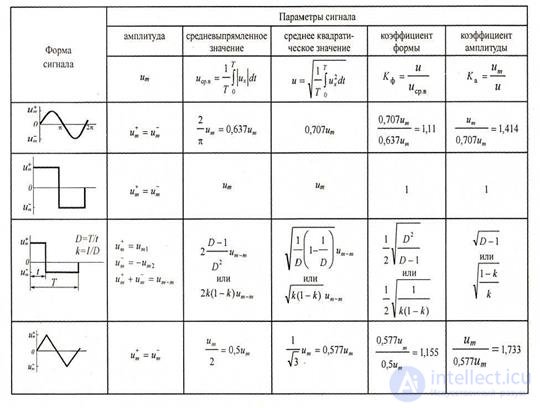
The values of these coefficients for the most commonly used types of signals and the ratios between them are given in Table. 2.3, where all voltages are labeled u for simplicity.
Table 2.3 Quantitative ratios between different values of a number of common signals
2.3.5 Block diagrams of analog voltmeters
Block diagrams of analog voltmeters are shown in Fig. 2.7. Currently, analog electronic voltmeters of direct current (Fig. 2.7, a) are of limited use, since they are much inferior in their technical properties to digital voltmeters. Therefore, further considered only analog AC voltmeters. Pictured in fig. 2.7, b block diagram is used in AC voltmeters to measure voltages of a significant level.
In order to ensure the required accuracy of a voltmeter to DC amplifiers used in electronic voltmeters, they impose stringent requirements with respect to the linearity of the amplitude characteristic, the constancy of the gain, the temperature and time drift of zero. When constructing electronic voltmeters for measuring small voltages, such requirements cannot always be satisfied.
Therefore, electronic AC voltmeters for measuring low voltages are performed according to the scheme shown in Fig. 2.7, c . This scheme is used in millivoltmeters, because it has great sensitivity. The latter is due to the presence of an additional AC amplifier.
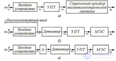
Figure 2.7 Block diagrams of analog electronic voltmeters: a - direct current; b - high level voltages; in - millivoltmeter
(UPT - DC amplifier;> - AC amplifier;
MES - magnetoelectric system)
When creating analog voltmeters, an important function is carried by AC / DC converters (detectors). Detectors can be classified according to the function of converting the input voltage to the output: amplitude (peak), mean square and average rectified values. The type of detector largely determines the properties of the device: voltmeters with amplitude detectors are the most high-frequency; voltmeters with rms detectors measure voltages of any shape; The average-volt meters measure only harmonic signals, but they are the simplest and most reliable.
Amplitude detector - a device whose voltage at the output corresponds to the maximum (amplitude) value of the measured voltage. In order for the detector load to effectively filter out the DC component and suppress high-frequency harmonics, the inequality 1 / (ωСф) << RH, where Сф is the filter capacitance, is necessary; RH is the load resistance of the detector. Another condition for good detector performance: the resistance of the RH load resistor must be significantly greater than the resistance of the diode in its direct conductance. In fig. 2.8 shows the principal and equivalent circuits and timing diagrams of the amplitude detector with parallel switching on of the diode (detector with a closed input). Consider the detector operation (Fig. 2.8, a) when the harmonic voltage uх (t) = Umsinωt is applied to its input .
At time intervals when a positive half-wave arrives at the detector input, capacitor C is charged through diode D, the resistance of which is low in the open state. The charge time constant τ3 = RaC is small and the capacitor charge to the maximum value Um occurs quickly. On the interval of the negative half-wave, the diode D is closed and the capacitor.
C is slowly discharged on the load resistance RH since it is chosen large enough. So, the discharge constant τр = RHС is significantly longer than the period T = 2π / ω of the input voltage. As a result, the capacitor remains charged up to the voltage Uc = Um = Uout.
The equivalent circuit of the amplitude detector and timing diagrams explaining its operation are shown in Fig. 2.8, b, c.
The change in voltage on the load resistance Rн is determined by the difference in amplitude of the input voltage Ux and the voltage on the capacitor Uc, i.e. UR = Ux - Uc. Thus, the output voltage UR will be pulsating with twice the amplitude of the measured voltage, as shown in fig. 2.7, c. This is confirmed by simple mathematical calculations:
U = Umsinωt - Uc ≈ Umsinωt - Um;
when sinωt = 1 voltage UR = 0; with sinωt = 0, UR = -Um; with sinωt = -1, UR = 2Um.

Figure 2.8 Amplitude detector with parallel diode:
a - schematic diagram; b - equivalent circuit; in - time diagrams
To isolate the constant component of the signal Um = - Uc, a capacitance filter is put at the detector output, which suppresses the other harmonics.
One of the advantages of analog voltmeters with an amplitude detector is the independence of the instrument readings from the waveform. Usually, the scale of the amplitude voltmeters is graduated in the mean square values of the sinusoidal voltage, i.e. instrument readings: Unp = Um1Ka.
The detector of the mean square value is a converter of alternating voltage into a constant, proportional to the square root of the mean square of the instantaneous value of the voltage. This means that the measurement of the effective voltage is associated with performing three successive operations: squaring the instantaneous value of the signal, averaging and extracting the root from the result of averaging (averaging is usually carried out when calibrating the scale of the voltmeter).
Squaring is performed by a semiconductor cell using a parabolic section of its characteristics, which is close in shape to a quadratic line; иногда этот участок создают искусственно.
In fig. 2.9,а представлена диодная ячейка D1R1c, в которой постоянное напряжение E1, приложено к диоду D1 таким образом, что он оказывается закрытым до тех пор, пока измеряемое напряжение ux(t) на резисторе R1 не превысит величины E1.
Следует иметь в виду, что начальный квадратичный участок вольтамперной характеристики полупроводникового диода имеет, как правило, малую протяженность (рис. 2.9,б), по этому эту часть удлиняют искусственно.
Линеаризация вольтамперной характеристики легко иллюстрируется методом кусочно-линейной аппроксимации. Для этого в схеме детектора используют несколько диодных ячеек (рис. 2.9,в) аналогичных показанной т рис, 2.9,а. Линейный участок обобщенной вольтамперной характеристики при этом увеличивается.
In fig. 2.10 показано, как получается в этом случае квадратичная характеристика при последовательном включении цепочек резисторов
R1c,R2c, R3с с диодами D1, D2, D3 .
Диод D1 первоначально закрыт напряжением Е1 затем, по мере роста напряжения ux(t) и достижения соотношения ux(t) > E1 он открывается и начальный линейный участок его идеализированной характеристики увеличивается.
В схеме, представленной на рис. 2.9,в, первоначально диоды D1, D2, D3 закрыты соответствующими напряжениями смещения Е1, Е2, Е3 и при малом входном напряжении ux(t) ток через миллиамперметр равен i0. Когда входное напряжение их(t) > Е1 откроется диод D1 и параллельно резисторуRo подключится делитель напряжения R1 R1c . As a result
крутизнавольтамперной характеристики на участке от Е1 до Е2 возрастает;
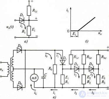
Рисунок 2.9 Детектор среднего квадратического значения: а - диодная ячейка; б - идеализированная характеристика;
в - схема квадратичного детектора
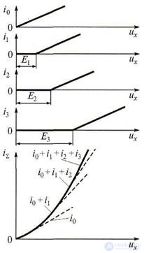
Рисунок 2.10 Аппроксимация квадратичной вольтамперной характеристики
суммарный ток протекающий через миллиамперметр, станет равным
i Σ = i 0 + i 1 . Когда выполнится условие ux(t) > Е2, откроется диод D2 и ток миллиамперметра будет равен i Σ = i 0 + i 1+ i 2. При ux(t) > Е3, откроется диод D3 и суммарный ток, протекающий через миллиамперметр, будет
equals i Σ = i 0 + i 1 + i 2 + i 3. As a result, the shape of the total
current-voltage characteristic approaches a quadratic curve. The meter reading will be proportional to the rms value of the input voltage, and it does not depend on its shape.
When constructing instruments of actual value, a number of difficulties arise, including the provision of a wide frequency range. However, these devices are the most popular, as they allow you to measure the voltage of any complex shape.
Детектор средневыпрямленного значения - устройство, преобразующее переменное напряжение в постоянный ток, пропорциональный средневыпрямленному значению напряжения. Структура выходного тока измерительного прибора с детектором средневыпрямленного значения аналогична ранее рассмотренному узлу выпрямительной системы. Аналоговый электронный вольтметр средневыпрямленного значения имеет более высокую чувствительность и меньшее потребление мощности от измерительной цепи (за счет дополнительного усиления), чем прибор со схемой выпрямления без усилителя.
Интегральные амплитудные детекторы . Диодные (как и транзисторные) амплитудные детекторы при малых напряжениях вносят в измеряемый сигнал значительные нелинейные искажения. Поэтому в измерительных устройствах применяют амплитудные детекторы на интегральных микросхемах - операционных усилителях - ОУ (рис. 2.10).
Поскольку детектор выполнен по инвертирующей схеме (возможно и неинвертирующее включение), то при подаче положительных полуволн напряжение u2 на выходе ОУ будет отрицательным. При этом диод VD1 открыт, а диод VD2 закрыт.
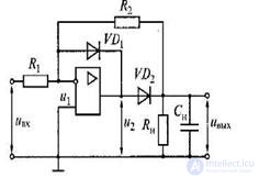
Рисунок 2.11 Амплитудный детектор на ОУ
Выход ОУ через малое прямое сопротивление диода VD1 подключен ко входу, что создает глубокую отрицательную обратную связь.
As a result, the voltage at the output of the op-amp is equal to the voltage at its input and is close to zero.
The output voltage of the detector is also zero. When a negative half-wave is applied, the voltage u2 at the output of the op-amp will be positive, therefore the diode VD1 is closed, and VD2 is open. In this case, the voltage at the outputs of the op-amp and detector uout = u2 - uBXR21R1 .
With a non-sinusoidal waveform, a methodical measurement error is possible.
12. What are the features of current measurement?

Comments
To leave a comment
METROLOGY AND ELECTROradio-measurement
Terms: METROLOGY AND ELECTROradio-measurement