Lecture
The principle of measurement . In the case of the pulse method of measurement, the distance to the damage site is determined by the time it takes for the so-called probe pulse, which is reflected in the line of damage, to be sent to the line back to it. The receiver is an oscillograph tube.
In fig. 9.6 shows three characteristic
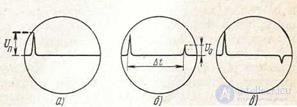
Figure 9.6 Typical cases of fixation of reflected pulses on the screen of a pulse device: a) ZH = ZC; b) ZH> ZC; ZH <ZC
the case of fixing the reflected pulses. If the circuit is homogeneous and its load ZH is equal to the characteristic resistance of the circuit Zс, then the pulse, passing through the circuit, is completely absorbed by the load and the reflected pulse does not occur (Fig. 9.6a). If ZH> ZC, the pulse energy will not be
completely absorbed by the load and a reflected pulse will appear with an amplitude U0 depending on the reflection coefficient. This impulse, propagating along the line, will come to its beginning after a certain period of time, determined by the velocity v of the electromagnetic wave propagating along the line and the distance Lx to the inhomogeneity sign of the reflected pulse at ZH> ZC coincides with the sign of the sent pulse (Fig. 9.6, b). If ZH <ZC, then a similarly generated reflected impulse will come to the beginning of the line with a different sign (Fig. 9.bv).
To be judged by fig. 9.6, b, c about the distance to the point of non-uniformity, it is enough to know the time Δt of the sweep of the tube’s beam from the beginning of the sending of the probe pulse (its leading edge) until the appearance of the (leading edge) reflected pulse. Then, if the velocity of propagation of pulses in a given line is equal to v, the distance to the point of non-uniformity is found from the formula.
lx = vΔt / 2, (9.12)
The speeds of propagation of pulses can be taken approximately equal to the above values of the speed of propagation of an electromagnetic wave, and the modules of wave resistances - from § 1.4. In practice, the speeds found for a given chain through preliminary experiments are mainly used.
The magnitude of the voltage of the reflected pulse Uo in the absence of a loss line is determined from the formula
U0 = Un [(Zn - Zc) / (Zn + Zc)], (9.13)
where Up - the amplitude of the sent pulse; Zn is the input impedance of the line at the point of violation of uniformity; Zc is the characteristic resistance of the circuit, and the value (Zn - Zc) (Zn + Zc) is the reflection coefficient. In the presence of losses, the amplitude of the reflected pulse acting on the beam of the receiving tube will decrease in e2al times, where a is the kilometric attenuation, Hn, for pulses of a given shape, and 1x is the distance from the beginning of the line to the point of non-uniformity. In practice, the reflection coefficient is usually determined by substituting in (9.13) the values of the moduli of the values of Zc and Zn putting fn = fs (see problems 91, 92). In addition, the magnitude of the reflection coefficient at the site of heterogeneity can be found from the magnitude of the observed amplitude of the reflected pulse, if you preliminarily capture a number of amplitudes of the reflected pulses at a certain gain, known reflection coefficients, at known distances and with a known attenuation of the circuit. Similar calibration curves are attached to some pulse devices (UIP4K, UIP5K, etc.).
Device pulse device . A pulse device designed to monitor the state of the line should have: a probe pulse generator (GZI, Fig. 9.7), a cathode ray tube (CRT) and a sweep generator (GR) controlling the horizontal movement of the beam. In addition, to determine the time Δt, you need a device for reading along the X axis of the time scale (or at a certain speed, immediately the distance scale). Such a device can be an additional generator, which gives calibration marks (in the form of small vertical outliers) - a scale mark generator (GM) with a certain constant frequency.

Figure 9.7 Simplified block diagram of a pulse device
Next, you need a limiting and matching device (O and SU), which, on the one hand, would limit the probe pulse when it is fed to the receiver, since its amplitude, quite large compared to reflected pulses, will overload the receiver and is inconvenient for observation, and on the other sides need a device that would provide the necessary consistency of the input resistance of the device with the line. Without such coordination, firstly, there will be false reflected pulses at the junction of the device with the line, and secondly, the reflected pulses, coming from the line, will again be reflected, will move along the line back and forth and distort the observed picture.
A receiving amplifier (PU), which could sufficiently amplify the incoming weak reflected pulses, and some control, master oscillator (SG), which would force all the blocks to work with the necessary synchronization, are also necessary.
It is essential to note that horizontal scanning is waiting. There are blocks (in Fig. 9.7 are not shown) with which you can both begin a sweep with a shift in time relative to the moment of sending a probe pulse to the line, and finish it with a certain,
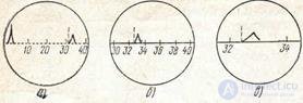
Figure 9.8 Determining the distance to the place of non-uniformity by marks on the screen of a pulse device: a) roughly; b) more precisely; c) more precisely
varying amount of time. Sweep speed is also adjustable. This makes it possible to observe not only the entire characteristic of the line as a whole, when the scanning speed is low and the calibration marks follow frequently, but also, at the option of measuring, to monitor the selected line segment on the screen. Noticing, for example, from the observed impulse response that the damage is between the fifth and sixth calibration marks (Fig. 9.8a), it is possible, to more accurately determine the position of the reflected pulse between these marks, to get; the distance between them is significantly increased. For this purpose, it is necessary to delay the scan for the time corresponding to the first five marks, and increase the scan rate (Fig. 9.8b, c).
It is possible at a certain speed and sweep delay and the time count Δt by combining the leading edge of the reflected pulse with the beginning of the probe pulse (device P5-5, [18]).

Comments
To leave a comment
METROLOGY AND ELECTROradio-measurement
Terms: METROLOGY AND ELECTROradio-measurement