Lecture
8 Measurement of electrical characteristics
Monitoring the state of the circuit with a direct current is intended to reveal how the primary parameters of the circuit correspond to the norms. Normalized: the resistance of the wires, the insulation of the wires relative to the earth and, consequently, between the wires, as well as the asymmetry (resistance difference) of the wires for direct current; for cable chains are also normalized working capacity.
For overhead lines, the insulation resistance of one kilometer of wire in relation to the ground must be at least 2 MΩ in any weather; at the same time, it should not differ from the same for another wire of the same circuit by more than 30%.
The asymmetry of the wires for direct current on the length of the reinforcement section should not exceed 2 ohms for non-ferrous metal circuits, 5 ohms for steel wires with diameters of 4 and 5 mm and 10 ohms for smaller diameters.
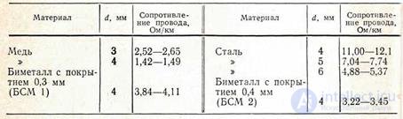
The normalized kilometric resistances of wires are given in [15, 16]. For some of them in the table. 8.1 shows the permissible resistances of the wire at a temperature of 20 ° C.
Table 8.1
The intent error for wire resistance and DC asymmetry should not exceed 0.5%; for insulation resistance up to 1000 MΩ - 5%; more than 1000 MΩ - 10%.
For balanced cables, the maximum allowable resistances of copper conductors at 20 ° C are given in Table. 8.2. They are calculated approximately from the expression R CL = 46 / d²
For aluminum chains, the resistance values Rl are greater than given in Table. 8.2 1.63 times (ρal / ρm = 0.0290 / 0.0178).
Table 8.2
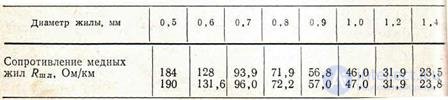
Note. The second line contains the data [L 15].
The asymmetry of wires in long-distance cables (R1 - R2) with a length of l km should not exceed 0.23√l / d2 for copper wires, and 0.37√l / d2 for aluminum wires. For cables of rural communication (in the area from the subscriber to the communication center) with a core diameter of 1 mm, the asymmetry should not exceed 3 Ohms, and more than 1 mm should not exceed 2 Ohms. The average value of the working capacity for intercity cables of star twist with cord-paper insulation at d = 1.2 mm 0.0275 microfarad / km and with cord-polystyrene insulation 0.0245 microfarad / km. For urban twisted pair cables with d = 0.5 μF, the working capacitance is 0.05 μF / km.
The insulation resistance of each core with respect to the rest connected to a grounded metal sheath (screen) at 20 ° C for cables with air-paper insulation (brand T) must be at least 2000m · km; cables with cord insulation (grades TZ and MKS) - 10 000 MOhm-km; for cables of rural communication (PRVPM type) - 25 MOhm-km.
The electrical strength of the insulation of high frequency cables between: all conductors, except for signal wires, connected in a bundle, and a grounded sheath (screen) is 2000 V (for low frequency cables - 1800 V); each living and the rest, connected in a bundle - 1500; all signaling wires interconnected and grounded sheath - 1000 V.
At a temperature of 20 ° C, the resistance of the inner conductor is 3.8 Ohm / km for cables 2.6 / 9.4 and 15.85 Ohm / km for cables 1.2 / 4.6; the resistance of the outer conductor is respectively 2 and 8 ohm / km. The insulation resistance between the inner and outer conductors for these cables is at least 10,000 MΩ-km. For more information about standards for different types of cables, see [15, 16].

Comments
To leave a comment
METROLOGY AND ELECTROradio-measurement
Terms: METROLOGY AND ELECTROradio-measurement