Lecture
Consider a simplified block diagram of a universal oscilloscope, shown in Fig. 4.1. In the scheme of this oscilloscope, in addition to the CRT, the following functional blocks can be distinguished: channels of vertical and horizontal deviations, a device for synchronizing and triggering a sweep, a channel for modulating a beam, auxiliary devices, a power source. In the oscilloscope, the electric signal under study is fed through a vertical deflection channel to a vertically deflecting CRT system, and the horizontal deflection of the electron beam of the tube is performed by a horizontal sweep voltage.
The cathode ray tube is a vacuum glass flask, inside which an electron gun, deflecting plates and a fluorescent screen are placed. The electron gun consists of a heated cathode K, a modulator (grid) of the brightness of the light spot M, focusing electrodes and acceleration of the electron beam - the focusing anode A1 of the accelerating anode A2 and the main anode A3., The brightness of the CRT phosphor is adjusted by changing the negative voltage on the modulator
M. Voltage at the first anode A1 focuses the electron beam into a narrow beam.
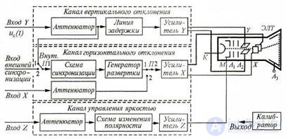
Figure 4.1 Simplified block diagram of a universal oscilloscope
In order to give the electrons the speed necessary for the luminescence of the phosphor, a sufficiently large (up to 2000 V) positive voltage is supplied to the second anode A2. For additional electron acceleration, an anode A3 is used, to which a high positive voltage is applied (up to 10 ... 15 kV).
Simplified operation of the deflecting systems of CRT can be explained as follows. An electron beam (beam) passes between two pairs of mutually perpendicular metal deflection plates: vertically deflecting Υ and horizontally deflecting X. If a voltage is applied to the deflecting plates, an electric field will exist between them that will cause the deflection of the electron beam to one side or the other. . When a voltage is applied to the vertical deflection plates, the spot will move along the Y axis; if the voltage is applied to horizontally deflecting plates, then the light spot on the tube screen will deflect along the X axis . If the electron beam is now focused in such a way that the light spot is located in the center of the CRT screen, then the signal under test is applied to the Y plates and the sawtooth voltage to the X plates, then under the combined influence of two voltages the beam will draw an oscillogram on the tube screen that reflects the input voltage from time.
The vertical beam deflection channel (see Fig. 4.1) is used to transmit the studied signal uc (t) to the Y CRT plates applied to the Y input. The vertical beam deflection channel contains an attenuator, a delay line and an amplifier Y. The attenuator allows you to attenuate the uc signal (t ) a certain number of times, and an adjustable delay line provides a small time shift of the signal on the CRT plates Y relative to the beginning of the sweep voltage Ux, which is important for the standby mode. Amplifier Y provides the amplitude of the signal on the plates Y, sufficient for a significant deflection of the beam on the screen even by the Kalym signal uc (t) under study. This amplifier contains an input amplifier with a variable gain and a paraphase (with anti-phase output signals of the same amplitude) amplifier, ensuring the position of the light spot in the center of the screen in the absence of the studied signals. The vertical beam deflection channel may also include an amplitude calibrator. The signal from the calibrator is fed to the input of the first amplifier to set the specified gain.
A switched-off coupling capacitor is also included in the input circuit of the vertical deviation channel, which allows, if necessary, eliminating the input to the oscilloscope of the constant component of the signal under study (the so-called "closed" input).
The horizontal deflection channel of the beam is used to create a horizontally deflecting - sweep - voltage Uх using a sweep generator voltage or to transmit (via an attenuator and amplifier) to the X plate of the test signal applied to the X input.
The timing circuit (and trigger sweep) controls the sweep generator and provides the multiplicity of the periods of the signal under investigation and sweep. To obtain a still image, the start of the sweep must be associated with the same characteristic point of the signal (front, amplitude maximum, etc.). This is achieved by synchronizing the sweep voltage with the signal voltage, so the sweep period must be equal to or a multiple of the signal period being studied: Traev = nТс, where n = 1,2, 3,4, ....
The sweep is the line that the beam draws on the screen in the absence of the signal under investigation as a result of the action of only one sweep voltage. The process of binding the sweep to the characteristic points of the signal is called synchronization in the self-oscillating mode of the generator and launching it in the waiting one. Synchronization and sweep start produce a special sync pulse supplied to the generator from the synchronization device.
The oscilloscope has two synchronization modes: internal (Internal) and external . With internal synchronization (switches P1 and P2 - in position 1), the sync pulses are generated from the amplified input signal before its delay. With external synchronization (switches P1 and P2 - in position 2) the synchronization signal is supplied from an external source to a special input X of the oscilloscope. For example, in standard pulse generators, clock pulses are generated, with respect to which the output signal can be shifted using an adjustable delay. The synchronization circuit generates a synchronization signal, which arrives at the sweep generator to obtain a clear, fixed waveform. A horizontal deflection channel amplifier X amplifies the sweep signal Up of the sweep generator and converts it to the sweep voltage Ux.
The horizontal deviation channel is characterized by sensitivity and bandwidth, which are almost two times less than in the vertical deviation channel. The main unit in the horizontal deflection channel is a sweep generator operating in continuous or standby mode. The form of the sawtooth voltage of the generator has a number of specific requirements:
• the return time of the beam must be much less than the time of forward travel, i.e. To5r. << Tpr; otherwise, part of the signal image will be missing;
• the sweep voltage at the direct path of the beam must be linear, otherwise the electron beam will move across the screen of the tube at different speeds and the uniformity of the time scale along the X axis will be disrupted. This can lead to a distortion of the signal under study.
The brightness control channel (modulation of the beam in terms of brightness) is intended to highlight the forward path of the beam. The backlight is performed by transmitting from the Z input to the control electrode (modulator M) a CRT signal modulating the beam flow and, therefore, the luminosity of the phosphor. The circuit of this channel includes: an attenuator, a polarity reversal circuit and a Z amplifier. A Z amplifier is used to form the required voltage level of the modulator. The amplifier can have an additional input, which allows the image to be modulated in terms of brightness by an external signal. Channel Z is also used to create luminance marks for measuring frequency and phase.
A calibrator is a voltage generator that forms a periodic pulse signal with a known amplitude, duration, and frequency for calibrating an oscilloscope, i.e. to ensure correct measurements of the parameters of the signal under study.
One of the main blocks of the oscilloscope is a CRT, the output elements of which are two pairs of plates deflecting the beam horizontally and vertically. If the sweep voltage is applied to one pair of deflection plates (usually to the X plates), then the sweep is called the sweep voltage form (for example, linear or sinusoidal ). If the sweep stresses are applied to the deflection plates of the X and Y tubes at the same time, then the name of the sweep is given in its form (for example, circular or elliptical ).
The most widely used linear sweep created by the sawtooth voltage Up, the sweep generator. In a linear sweep, the beam, moving uniformly across the screen, draws a straight horizontal line, as if plotting the abscissa axis of the Cartesian coordinate system — the time axis. Depending on the operating mode of the sweep generator, such a sweep is divided into self-oscillating, waiting and one-time.
Self-oscillatory sweep - sweep, in which the sweep generator is periodically started (automatically) and in the absence of a trigger signal at its input.
Waiting sweep - sweep, in which the sweep generator is started only with a trigger signal.
Single sweep - sweep, with which the sweep generator is run once with subsequent blocking. Such a scan is used to observe single and non-periodic processes and when photographing non-repeating signals from the oscilloscope screen.
When applying voltage uх = uр of a sawtooth form to horizontal deflecting plates (Fig. 4.2), the electron beam under the influence of this voltage moves from left to right in the interval Tpr (points 0-1-2 is the duration of the forward path of the beam) and from right to left in the interval To6p (points 2-3 - the duration of the return path of the beam). Moreover, the speed of movement of the beam in the opposite direction is much greater (usually the beam is extinguished in this case) than in the forward direction. With the help of the voltage sweep applied to the horizontal plates of a CRT (X plate) of the oscilloscope, on its screen one can observe the signal under study, which arrives at the Y plates and changes over time (unwrapped in time).
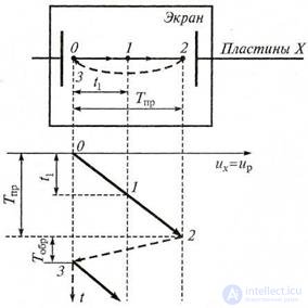
Figure 4.2 A diagram explaining the creation of a time scale along the horizontal axis of a CRT screen:
→ - direct path of the beam; → - reverse beam
Traz = Tpr + Tobr ; T CR = 2 t 1, (4.1)
The self-oscillation (continuous) scan is used to study periodic signals, as well as pulsed ones with a small duty cycle q = Tc / τ. It is included during internal synchronization. In fig. 4.2 presents the studied pulses u of duration τ each, sweeping the synchronous voltage ux and the observed waveform (in frame). The periods of watering the pulses and the sweeping voltage are equal to each other: Tc = Tr.
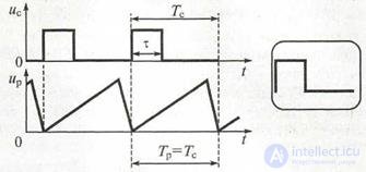
Figure 4.2 Self-oscillatory sweep
Using the self-oscillatory sweep, it is almost impossible to observe non-periodic signals, and it is virtually useless when observing periodic short pulse signals with a high duty cycle q (this is due to the fact that the front and rear edges of the pulse almost merge). In these cases, use the waiting scan.
A typical example of a waiting sweep is shown in Fig. 4.3. The sweep generator is triggered only when pulses of uc are received. If a
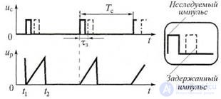
Figure 4.3. Waist sweep application example.
the scan time t2 - t1 is comparable to the duration of the pulse being studied, its image on the screen is quite detailed. In the oscilloscope, due to the inertia of the generator, the onset of the waiting sweep can be somewhat delayed relative to the pulse front us. Therefore, if the pulse front is very short, then it may not be displayed on the waveform. To observe a short front, the signal u is delayed by τ3 in time in channel Y using a delay line (dashed pulses u in Fig. 4.3). The observed waveform is given together with a non-delayed pulse in Fig. 4.3 by a dashed line (framed).
Sinusoidal scan. In a number of measurement tasks, for example, when measuring frequency, or phase difference, instead of a sawtooth sweep voltage (linear sweep), a sinusoidal sweep is used. To obtain a sinusoidal sweep, the plates X are supplied with a voltage varying according to the harmonic law ux (t) = Umx sin ωt. In this case, the oscilloscope linear sweep generator is disconnected. A positive half-period of the voltage of a sinusoidal sweep causes the beam to move from the center of the screen to its right boundary and back; negative half-period - from the center of the screen to its left border and back to the center. The speed of movement of the beam varies sinusoidally, although the scan line is a horizontal line.
Circular scan . To obtain a circular scan on a CRT screen, a sinusoidal signal uy = Usinωt = Usin (2πt / T) is applied to the Y plates, and a signal similar in shape and amplitude but delayed by a quarter period (in phase by φ = 90 °) is fed to the X plates i.e. their - Usin [ω (t - T / 4)] = - cos ωt. The oscillogram of the circular scan is shown in Fig. 4.4. Under the action of the sweeps uy and ux, the beam draws a circle on the CRT screen over the period T. The position of the beam on the screen at time t = 0 is marked by point 0, at time t1 by point 1, and so on.
Elliptical scan . If, when using a circular scan, the amplitudes of the signals uy and ux are not equal, then the circle is distorted and an ellipse is observed on the screen, i.e. an elliptical scan occurs.
For example, with u
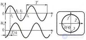
Figure 4.4 Obtaining a circular scan in an oscilloscope

Comments
To leave a comment
METROLOGY AND ELECTROradio-measurement
Terms: METROLOGY AND ELECTROradio-measurement