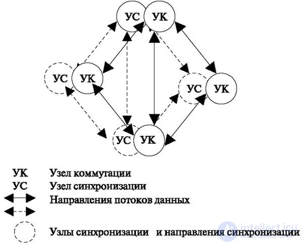
This method is shown in Fig. 8.15. This is where a synchronization service network is created, which is used to synchronize reference oscillators at communication sites. With such a decision, the high costs of creating such a network are inevitable.
Fig. 8.15. Using the switching node synchronization service
Force sync
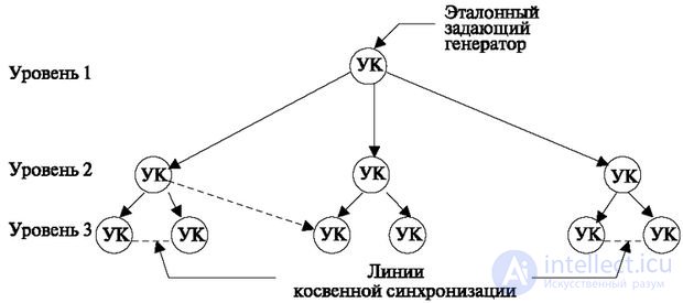
This method is called the hierarchical method and is shown in Fig. 8.16.
Fig. 8.16. Forced synchronization of switching nodes
In this case, a hierarchical system (preferably coinciding with the switching network hierarchy) of synchronization is created, where the “upper level nodes” transmit the reference frequency to the “lower level nodes”. This is possible in two ways - direct and indirect. With the direct method, a separate synchronization line is allocated. Such an approach essentially forms a synchronization network.
In the indirect method, the lower-level reference generator synchronizes its reference generator from the upper-level generator through channels, extracting clock pulses from the digital data and speech stream, as was already discussed in previous sections.
On real networks, a mixed method is used: some of the network nodes are configured in a direct way, some indirectly. This is determined by technical and economic analysis.
All substations of one station, all subscriber systems of digital compaction use the system of forced synchronization from the station.
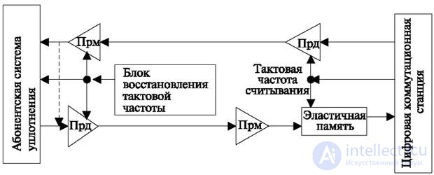
In this case, a situation arises, which is called "clock speed". This principle of operation is shown in Fig. 8.17 [5].
This picture shows a subscriber packing system with a receiver (PFP) and transmitter (Tx) and a station with similar equipment. The station sends a stream of speech and data that is synchronized in frequency with its reference oscillator. Using this stream, the subscriber system synchronizes its generator and responds with a digital stream. This stream contains all the distortions that have occurred in the process from the station to the subscriber system, in particular, phase distortion due to the propagation time of the transmission. The station receives the distorted stream and restores it. In this case, in order to prevent distortions on the side of the station, when accepting the incoming stream with the clock sequence passed through the loop, an "elastic memory" is used, as shown in Fig. 8.17. This allows the procedure to restore the clock frequency only on the side of the station and thus makes it possible to install simplified equipment at the substation.
Fig. 8.17. The junction between the subscriber seal system line and the digital station.
Brief summary
- Telephone networks are a set of terminal devices (terminals) of telephone exchanges, lines and channels of the telephone network, and transit switching nodes.
- The initial phase of building a communications network is characterized by a configuration where each station communicates with another telephone exchange on the principle of “each with each”
- The disadvantages of the network according to the “every with each” principle are a large number of directions and a corresponding number of poorly used connecting lines. Because of this, on large networks, zoned networks with incoming and outgoing message nodes are used.
- For the rural network is characterized by a small specific concentration of subscribers. Concentrating stations are usually located in large villages, and the problem is that the installation of small stations is necessary and the station concentrating the load must have terminal capacity and at the same time be transit.
- On the rural network, the following types of stations are distinguished: terminal station (OS), central station (CS), and junction stations (CS).
- Long-distance networks are built on a hierarchical basis. At the lower level are Automatic Intercity Stations (AMTS). All AMTS are included in the Node 2 Automatic Switching Nodes (UAK2). The main load between the zones passes along the lines between UAK2. All excess load passes through UAK1, which are connected according to the principle “every with each” and designed for transmission of the telephone load with small losses.
- When connected directly to the station, the length of the subscriber line can be very large, since the specific concentration of subscribers in a small radius from the station is small. Therefore, all modern stations allow the construction of a network based on the distributed equipment of one station of subscribers. This reduces the length of subscriber lines and decreases their number.
- The existing public network and the above described network architecture had the following disadvantages: rigid assignment of the number to physical equipment, separation of network elements according to functional features. The principle of building a network implies that it belongs to one company that provides access control, operation and load administration.
- Software control allows you to take into account network features that arise when telecommunication services are provided by several operators.
- The numbering system (addressing) is one of the fundamental characteristics of the network. It is currently being upgraded due to the emergence or expansion of new networks.
- In fixed telephone networks in the Russian Federation, there are two numbering plans - open and closed.
- In case of closed numbering plan, subscribers are assigned permanent numbers, the value of which does not depend on the position of the calling subscriber (subscriber B).
- An open numbering plan is characterized by the fact that the number of characters depends on the connection route.
- On the city network, only closed 5,6,7-digit numbering is used. The subscriber number is formed within the 10,000th group (0000-9999) with the addition in front of them of the code defining this ten thousandth group.
- The national (significant) telephone number uniquely identifies the end element of a local telephone network or a mobile network within the territory of the Russian Federation.
- To use automatic long-distance telephone communication, it is currently necessary to dial the number 8-ABC ab xxxxx. In the future, to establish an international telephone connection, the PMN indicator is used, which is an international prefix, which is formed by two decimal places having the value "00".
- The maximum attenuation between two telephone sets should not exceed 28 dB. In this case, the attenuation of subscriber lines should not exceed 4.5 dB.
- Attenuation on the intrazonal network from the telephone to the station, where the transition to the four-wire path (AMTS, UVS, UIS) is carried out, should not exceed 9.5 dB.
- The quality of telephone call service on the urban telephone network is determined by the probability of loss or denial of service due to the lack of free and accessible switching devices and channels.
- The total estimated losses for GTS subscribers should not exceed 0.030, when communicating with the suburban area and private PBXs - 0.040, and when communicating with PBXs with telephone stations - 0.005. The probability of losses includes the probability of occupancy of the inputs of switching equipment, control devices, devices for receiving and transmitting signals, internal blocking of devices of lines and channels. In case of losses due to waiting beyond the allowable time, the same standards can be adopted by setting a maximum waiting time.
- The basic concepts that make up a routing definition are: endpoint, endpoint code, charging zone, route, direction, or group of channels (lines).
- Routing algorithms must provide paths with the smallest number of transits between outgoing and incoming connection points when performing a given quality of service.
- With mutual synchronization, the total synchronization frequency is established due to the fact that all nodes in the network exchange reference frequencies.
- When using a single synchronization service, a synchronization service network is created, which is used to synchronize reference oscillators at communication sites.
- In the case of forced synchronization of switching nodes, a hierarchical system is created (preferably coinciding with the switching network hierarchy) of synchronization, where the “upper level nodes” transmit the reference frequency to the “lower level nodes”.

Comments
To leave a comment
Telecommunication Services and Devices
Terms: Telecommunication Services and Devices