Lecture
Consider a distributed system where the service equipment and functions are distributed in modules [57]. Each of the modules has a limited capacity and performs certain functions. This allows you to have a system that adapts flexibly in both capacity and function.
The basis of such a system is the concept of "module". The modules have already been mentioned in "Telecommunication stations. Switching fields and control types". The main feature of the module is that it allows a huge variety of external terminals and protocols to lead to a single type adopted for transmission and processing in this switching system. There is a simultaneous agreement of two streams - information and signaling (exchange protocols).
The information flow implies a transition from different types of paths (digital asynchronous and synchronous, analog and others) to the same type used within the system (currently it is a synchronous digital path).
Signaling flow causes multiple signaling systems (for example, analog or DSS signaling, discussed in the ISDN section) to a single view (at present, this is similar to a separate signaling channel, which will be discussed later). To accomplish these goals, the standard type of module looks as follows (Fig. 2.15).
The module contains two parts - one terminal, the second controlling (Fig. 2.15a).
The task of the terminal part is the interaction with external sources of a given type and the transformation of the information flow to the in-station view.
The terminal part selects (or sets in the opposite direction) the signals of interaction and control from / to an external source and transmits them in the control channel (in some systems via control buses) to the control part of the terminal.
The controlling part of the terminal contains a universal computer with resources sufficient for processing tasks that come from sources included in this module.
The software of this computer can be divided into two parts:
The composition and scope of this provision has a fixed part for servicing sources and standard interaction. Depending on the capacity and the tasks performed by the system, the backup resources (memory and time) may be occupied by group-wide or system-wide tasks.
In large stations, to solve problems not related to specific sources, group (for example, subscriber services module for a group of analog subscriber modules) or system-wide modules (for example, a routing task) can be allocated. Since such tasks are not related to processing signals of the physical interface, they contain only the control part.
There are two parts to the control equipment:
In fig. 2.16b shows the main components, processor and memory. In fig. 2.16 in shows the symbol of this module. The gray part corresponds to the part containing the control and switching parts.
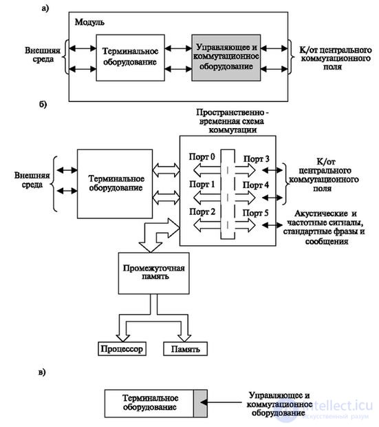
The switching field of the module commutes information flows to the central switching field and control information to the processor.
The processor is connected via an intermediate memory (to ensure synchronization) to one of the ports of the switching field.
This allows it to directly connect to the central field and transfer necessary control signals to external sources. In addition, if there is a special operating system, it can have access to the memory of another module, which creates great software capabilities and increases the possibility of increasing resources.
The number of information ports is two (both towards the terminal equipment and towards the central field). This increases the required reliability of the system. Another port is used to connect digital signals that can be converted to standard acoustic signals (station answer, busy, call control) in the module, as well as to transmit sound announcements (for example, the subscriber is out of service ") or standard phrases recorded by the subscriber.
A block diagram of a station with fully distributed control is shown in Fig. 2.17.
In fig. 2.17 shows one of the possible options for the layout of the station. A set of modules allows you to implement in-station connection.
The figure does not show the modules of ringing signals and maintenance, which are a mandatory accessory of the station and are present in any quantity with any configuration.
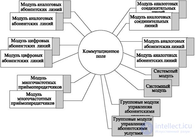
We list the tasks shown in the figure modules.
The module of analog subscriber lines is designed to interact with this type of line, receives and converts the signals "the subscriber picked up the phone", "the subscriber hung up". Transmits to the subscriber's side acoustic signals "station response", "making a call", "controlling a call", "busy", etc. All of them, except the ringing signal, are connected to the module input. The signal "making a call" due to the relatively high voltage is switched in the subscriber module. There are also connected some circuits that control the parameters of the subscriber loop (subscriber set will be discussed later).
Module digital subscriber lines. This type of module is designed to work with digital subscriber lines. It also provides the exchange of signals when installing digital lines and when servicing the line.
Analog connecting line module. The module is designed to work with existing stations that transmit information in analog form. The kit will be discussed in section 2.6.
Digital path module. It provides work with digital paths. The most common are kits for working with pulse code modulation (PCM) systems.
Multi-frequency transceiver module. The module is used for in-station communication for accepting dialing signals from the frequency dialer. For incoming and outgoing communication, it provides the transmission of control signals to the stations of the coordinate system (for example, ATS-KU).
Next is a group of modules that do not contain the terminal part. These are processors that perform certain tasks. In the drawings they are painted in gray.
Group modules for managing subscriber services. They control the main and additional types of services: for example, they check the subscriber’s ability to use "outgoing communication" (if he belongs to a subscriber group), whether a call can be forwarded to him, etc. In low-capacity stations these modules are not used, and Functions are distributed to other modules.
System module It monitors the availability of resources in the system (for example, if there are several multifrequency transceiver modules, it collects information about the presence of a free transceiver in them). It performs system tasks, for example, choosing the direction and route, billing.
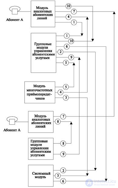
Let us now consider the algorithm of the work of this system when establishing an internal station connection (Fig. 2.18).
After the connection is established, the caller's number is sent.

Comments
To leave a comment
Telecommunication Services and Devices
Terms: Telecommunication Services and Devices