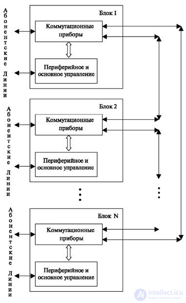
For such a method (Fig. 1.16), the connection of blocks directly with each other without the use of a central switching field is characteristic. Then each module has a bundle of lines or digital paths connecting it with every other module. Inside the module, we must have in the required volume the steps of concentration and mixing, the latter is designed to access the necessary beam of lines. When establishing a connection within a module, the direction (module number) in which the connection is established must be determined.
enlarge image
Fig. 1.16. Block diagram of a decentralized station with direct links between blocks
In addition, we are dealing with separated beams, i.e., the entire load is broken in different directions. In this case, the use of inter-station lines is reduced: the greater the capacity of the station (the number of modules), the smaller the beams of lines, which is inconvenient when building up.
The solution without the use of a switching field was allowed in the first versions of the Italtel Linea UT system. The magnitude of the module was adopted at the same time 2000 numbers, the maximum number of modules was 16.
Station using central switching field
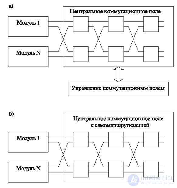
For inter-module switching using all outputs of the modules, a switching field is established. The latter requires installation 1.16. A block diagram of a decentralized station with direct connections between blocks of a special control device for switching control is shown in Fig. 1.17a.
Fig. 1.17. Decentralized control: a) using a switching field processor b) with self-routing
Switching field with self-routing
The presence of a switching field processor violates decentralization, since an element appears, at the failure of which the entire station fails. Therefore, the switching field at least duplicated, and in some systems put as many as 4 blocks. In normal mode, all of these units operate in load sharing mode, which improves the quality of service.
One of the achievements of the construction of telephone exchanges was the development of a system with self-routing. Such a system does not require a processor that controls the search for paths in a switching field, decentralizes control, increases reliability and allows a gradual increase in the switching field. A variant of this field is shown in Fig. 1.17b, the principle of its work will be discussed below. The division of stations into modules requires the exchange of signals within the station; therefore, the following options for organizing such an alarm arise at the block diagram level:
- The use of alarm inside the information channel.
- Selection of a separate signal channel:
- fixed;
- switched through a separate switch (usually a message switch).
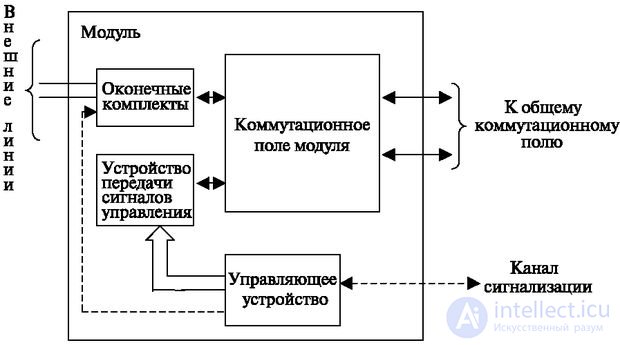
In fig. 1.18 shows a general view of the module.
The structure of the module is typical for all types of stations. The module consists of a typical control part - the switching field and the processor. Kits in each type of module may vary. They perform the task of coordination with the external environment and assemble the module depending on its task.
Fig. 1.18. General principle of station module construction
The switching field of the module can be single-link (S-12 system), distributed in steps, containing subscriber and group part (in the EWSD system - DU and CDU steps) and multi-link to provide access to directions leading to different blocks (Linea UT system). The principles of the use of modules when establishing a connection are considered in the "Switching fields on the microelectronic element base".
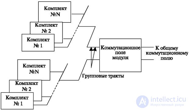
The sets are controlled from the module processor either over a separate group of buses or through one of the channels of the path connecting the sets with the switching field. The principle of the inclusion of kits (Fig. 1.19) demonstrates the integration of kits into groups and connection to a group path.
Fig. 1.19. The principle of connecting kits to the subscriber field of the module
It usually contains 32 channels, one of which is for signaling. The same channel can be used for receiving and transmitting control signals for peripheral devices. Two groups of paths for layout allow you to apply different backup conditions.
In fig. 1.19 shows two options for connecting the signal channel.
One of the options is that the alarm device is included in the switching field of the module. This allows you to switch outgoing signals from it to any channel of any output. Typically, a fixed channel is used for signaling. As a rule, this is the 16th channel, however, it can be used as fixed and other channels.
The signaling device itself implements signal processing at the first and second levels. Recall that this includes synchronization, error correction and re-queries. Logical operations are performed by the module's processor.
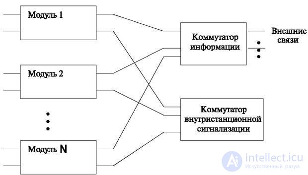
The dashed line shows the direct output of the signal channel from the processor. In this case, along with the information switch, an inter-station signaling switch can be used. Its task is to switch signaling channels and information between modules.
One of the possible goals of such a separation of signaling channels can be their use for transmitting information in the form of messages.
In some systems (for example, ESS No. 5), the alarm goes through a fixed channel, but at the input of the switching field it is allocated for switching through the message switch.
In fig. 1.20 shows a general view of the modular station with two types of switching - information and signal.
Fig. 1.20. The principle of operation of modules with separate signaling switches
Brief summary
- All telephone exchanges contain certain groups of devices: switching field, control devices, subscriber lines, inter-station lines, display devices and maintenance.
- The switching field realizes the tasks of connecting two or several sources among themselves.
- The control unit solves the logical tasks necessary to establish the connection, and also performs the tasks associated with the main and additional services.
- It is characteristic of a fully accessible switching field that each source included in its input can be connected to a source included in the output.
- Such fully accessible principles for the construction of the switching field were not widely used because of their inefficiency for high-capacity stations. Recently, in many important switching applications, software methods are used that are executed on computers. These switching methods are equivalent to a full-access scheme.
- With a large number of users, switching circuits containing many links are more efficient.
- For inter-office lines, the cost of which is very high, it is necessary to increase the intensity of use and thereby reduce the requirements for the number of lines allocated to a given group of subscribers. Therefore, special schemes with concentration are used to switch on subscriber lines.
- The transition from single-link switching circuits to multi-link circuits creates a new phenomenon - blocking. Under the block means the impossibility of establishing a connection from a given input to a free output due to the lack of free intermediate lines.
- For schemes with any number of links that have locks, a conditional search method is applied. Therefore, the choice of each free line is determined by the freedom of the path as a whole. In the case of a conditioned search, the search for paths occurs in two stages.
- Accessibility is the number of paths (each of which may consist of several lines) leading from one entrance to the desired exits.
- Possible search options from input to output are classified as: free searching, when any output of the switching field is looked for, with which it is necessary to perform switching; group search when searching for any exit, but in a certain group; forced search, when the intermediate line is searched for only one of the exits.
- Direct is the control, in which the station is controlled directly by signals transmitted from the subscriber terminal (telephone).
- Signals transmitted between registers and control devices (in the coordinate PBX, these are markers) are called control signals. The control signals provide information about the dialed digits (the address of the end point), as well as information about the progress of the connection.
- With centralized management, the constant component of the equipment is always large, which is installed at the station regardless of capacity.
- To limit the consequences of losing operational information, the “traffic sharing” duplication method is used. In this case, each of the control devices in normal mode works with its equipment. In the event of an accident, the working computer takes over the entire load.
- To reduce the transition time to the reserve and eliminate information loss, the most common is the system of "duplication with synchronization". In this case, the signals from the external environment come to both control devices, and the external environment control commands are normally sent from one device. In emergency mode, a working device works without the need to correct information.
- Hierarchical control systems are an intermediate type between centralized and decentralized management methods. In "pure form" it is rarely used. In this case, all tasks are divided into hierarchy levels and distributed among processors.
- The system is divided into modules, each module is designed to serve a limited group of external sources or to perform a limited task, each station is recruited from such modules in accordance with the capacity and tasks required at the moment.
- The direct connection of blocks is the connection directly with each other without the use of a central switching field. Then each module has a bundle of lines or digital paths connecting it with every other module.
- In stations using a central switching field for inter-module switching using all outputs of the modules, a switching field is established.
- A system with self-routing does not require a processor that controls the search for paths in a switching field, decentralizes control, increases reliability, and allows a gradual increase in the switching field.
- The structure of the module is typical for all types of stations. The module consists of a typical control part - the switching field and the processor. Kits in each type of module may vary. They perform the task of coordination with the external environment and assemble the module depending on its task.

Comments
To leave a comment
Telecommunication Services and Devices
Terms: Telecommunication Services and Devices