Lecture
The block diagram of this algorithm is shown in Fig. 3.11.
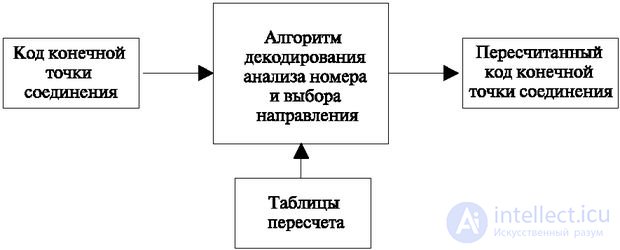
At the entrance receives information that must be converted to another form. Recounting one number or a set of numbers into others is a fairly common operation in switching technology. In particular, it is caused by the ambiguity of the numbering system of the same device at the telephone exchange. For example, a subscriber set may have the following numbers:
In the process of establishing a connection, all these numbers can be recalculated one to another. When developing a PBX, they always try to streamline the relationship between numbering. The existence of a law during such a transition significantly saves resources, but, unfortunately, most often such a law is absent.
A very simple algorithm for recalculation is single-stage decryption using a table, when each source number to be recalculated is assigned one row of the table, into which a corresponding number is written in another numbering system.
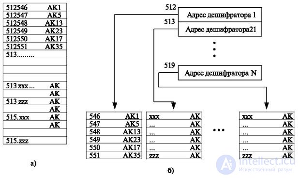
Such an example is shown in fig. 3.12a. This decoder is designed to determine the sequence number of the subscriber set. Each line is associated with a list number (for example, 512546), in which the corresponding sequence number of the subscriber set (in this case, AK-1) is written.
Significant impact on the decryption algorithms have the requirements of increasing the station during operation. For the convenience of expanding the station during operation, two-stage or multi-stage addressing is often introduced (see Fig. 3.12b).
On modern nodal networks, the number of possible combinations of the first digits of the subscriber number significantly exceeds the number of directions from each station. Each PBX can be included in the outgoing message node. At the same time, external links go only through the node. Thus, the number of external directions is 1, and if the subscriber number of the network contains 6-7 characters, then the single-stage numbering will lead to a huge amount of inefficiently used memory.
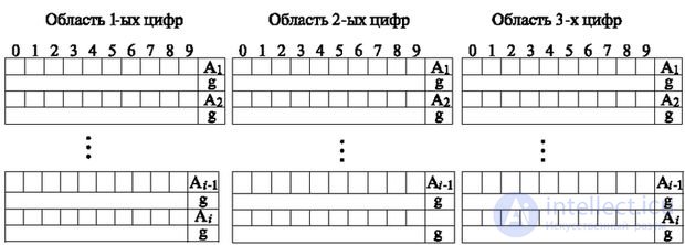
Given the above, to reduce the amount of recalculation, you can apply a consistent principle of analysis. With this method, each individual digit is sequentially analyzed.
The results of this analysis may be as follows:
For the algorithm that implements this method, memory arrays of the analysis of the first, second, third, and so on digits of the number are organized (Fig. 3.13). Each zone of the memory array contains two words (in Figure 3.13, only the zones of the first digit array are shown). The first word contains the standard with which the i-digit of the number will be compared, and the address (A1, A2, ..., An) of the next word in the array zone of the first digits. In this zone there is another standard, the comparison with which is carried out in case the previous standard coincides with the i-digit number. If such a coincidence occurred, the second word can contain one of two types of information: the number of directions or the address of the array of the next (i +1) -digit, with the standards of which it is necessary to consistently compare this figure.
The standard is a ten-bit word with information recorded positionally. Recall that in the position code each digit from 0 to 9 corresponds to one binary digit, the unit value of which indicates the presence of this digit in the word.
The module that implements this algorithm uses as input the application from the algorithm for receiving the number (the address of the zone where the numbers are accumulated). The result of his work is the number of directions.
The algorithm is configured (see Fig. 3.13) on the basis of tables, list numbers and corresponding directions. He performs a number of the following actions (Fig. 3.14). The algorithm begins with reading the application. Then set the index i = 0 (operator 2), corresponding to the first digit of the number. Further, this figure is read (operator 3) and decoded into a position number (operator 4), after which the standard (E i ) - (operator 5) is read and checked bit by bit for coincidence (operator 6) with the position value of the number (N).
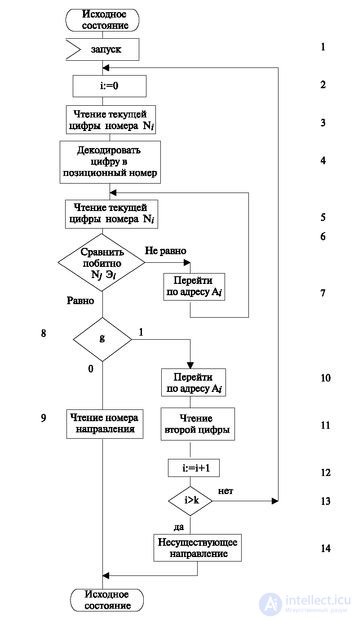
If the coincidence of the position number and the reference is obtained, then the sign in the second word of the reference is checked (operator 8). The value g = 0 indicates that the word contains the number of the direction that is entered into the working cell (operator 9) and is the result of the algorithm.
If the figure does not match the standard, then the address of the zone and the standard located in this zone (operator 7) is read from the first word of the standard and the process is repeated.
When a digit coincides with a reference and when g = 1, the next digit is read, and the second digit is the reference whose address is specified in the second word of the zone (i: = i + 1 operator 12). At the same time, it is checked whether the index (i + 1) (operator 13) exceeds the number of digits specified on the network. If it does not exceed, the next digit is read and the process repeats. Otherwise, it is noted that the dialed number corresponds to a nonexistent direction (operator 14).
Consider a specific example. In fig. 3.15 shows the network connections of the station, indicated by the number 1. From it to other PBXs there are six directions, indicated by six-digit numbers. The first two directions are characterized by one sign, one direction - by two signs, the other three - by three signs.

Further on fig. 3.16 shows the memory zones corresponding to this network.
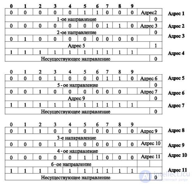
At address 1 in the standard, the value 1 is marked with positions 5 and 6, corresponding to the first direction. The number of this direction is recorded in the second word (g = 0). The right part of the first word contains the address of the second zone (address 2), used when the numbers do not coincide with the standard. The value 1 in the standard of address 2 marks positions 7 and 8, corresponding to the second direction. The sign g = 1 in the word with address 3 indicates that in case of coincidence of the position number of the digit and at least one digit of the standard it is necessary to go to the standard of the array of second digits at 5. This transition is dictated by the fact that the first digit with the value 1 does not allow direction, since the four directions (from the third to the sixth) are characterized by numbers starting with 1 (see Fig. 2.12). At the end of each array of numbers there is a standard containing all units.
It ensures that digits that are not recalculated to the number of the direction or not redirected to other cells will not lead the station to a deadlock situation. Such figures are attributed index "non-existent direction." Actions for such source data are already displayed in the general analysis algorithm (Fig. 3.14).
Interaction with the central algorithm consists in launching the operation of this algorithm with an indication of the place of information that is to be decoded. The most massive case is the recalculation of the dialed number into the number of the connection establishment direction. In this case, an application is given indicating the memory area of the process where the information is located, and an indication of the place where the number of the found direction should be recorded.

Comments
To leave a comment
Telecommunication Services and Devices
Terms: Telecommunication Services and Devices