Lecture
So, as we found out, there are many specific algorithms that perform scanning processes. Anyone interested in a more detailed acquaintance with this issue, we can recommend a number of references [31], [9]. These books contain descriptions of algorithms that are not presented in this course. Below are summarized conclusions from these sources that meet the most stringent requirements for service calls.
The scanning algorithm is shown in Fig. 3.4. In this figure, the following notation:
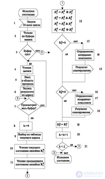
The remaining variables R 3 K , R 4 K , R 5 K , R 6 K - are calculated in the course of the work of the algorithms and explained in the course of its consideration.
The superscript in the algorithm means the current number of the serviced line, which is changed in accordance with the operator 20 of this algorithm.
It starts with a periodic start of the timer. In this case, a triggering period of 10 ms is chosen, which guarantees reading the shortest signal (disk dialing pulse) from 2 to 3 times. Multiple polling further allows us to distinguish a real signal from a noise.
At the beginning of the algorithm are the operators 1-7, processing the buffer applications from already started processes. Such a priority in processing allows us not to put new requests on service in order to avoid overloading the processing algorithms. This part of the algorithm determines the presence of signals that the process stopped after the transition waits for. The algorithm delivers the signal INPUT to the process.
The second section contains operators 8-12, identifying the presence of changes in the state of the environment. The principle of its operation lies in the fact that the previous state of the R1 lines and the subsequent R2 lines are compared and it is determined whether there are any changes from the previous point in time.
For example, if in some 10 millisecond cycle k:
R 1 = 00101101, and
R 2 = 10010101, then
 .
.
Discharges of the result, equal to one, indicate the presence of a change, and one should pay attention to the fact that two types of transition are noted - from 1 to 0 and from 0 to 1.
Next, the blocked polling points should be separated. For this, an array of {R 0 } locks is formed. One word from this array R 0 is read. In it, 0 indicates that the scan point is blocked, and 1 indicates that it is in operation and multiply bitwise by the result of the previous operation (R 3 ):
R 3 = 10111000
R 0 = 11001111
R 4 = R 3 & R 0 = 10001000.
For many processes, it is not only information about the presence of a change that is important; it is also necessary to distinguish its type. For example, a transition from 0 to 1 indicates a call, and the reverse - a release. When receiving a number, the fixation of a digit can occur either on the leading edge of the pulse, or on the rear (but not two). In this regard, the following actions are performed. The digits are separated, meaning a transition from 0 to 1. To do this, with the operators R 4 and R 2 , an operation of bitwise conjunction is performed:
R 4 = 10001000
R 2 = 10010101
R 5 = R 4 & R 2 = 1,000,000
A single unit indicates the desired transition.
Next, the bits that change their value from 1 to 0 are checked:
R 4 = 10001000
R 5 = 10,000,000

The unit value of digits corresponds to the above transition.
The following operators (13-18) provide the coordinates of the sets in which changes occurred.
When scanning with protection, the scan result contains an application for rescanning (not shown in Fig. 3.4). Re-scanning determines whether a steady change has occurred during the two previous cycles.
After that, each word in the array of previous states is assigned the value of the current one to prepare subsequent cycles (operator 19).
Further actions (from 20 to 21) are associated with the transition to the next scan line or the completion of the process when checking the last ruler.
The algorithm ends with a transition to the initial state.
The considered algorithm in accordance with the general model performs the operator EXIT. He forms and transmits commands to the external environment. In modern systems, such commands are transmitted to the following devices:
This kind of work requires the transmission of high-power analog signals or low impedance contacts that switch signals. Despite the progress of technology, contacts will not soon be replaced by other means. The windings, the control relays, are arranged in special lines, and the signals coming from the processor are recoded and, if necessary, amplified. Features of the transfer of commands to such devices due to the fact that switching objects have a relatively large response time and release time, much more processor speed. Therefore, when transferring commands, it is usually inefficient to wait for a reaction, and it is advisable to return to the process after a period of time sufficient for the device to execute a command.
A device that executes commands for a time exceeding the speed of the processor will be called slow.
Switching fields, as a rule, contain several cascades. Therefore, control commands are transmitted in cascades.
At the beginning of this lecture, we agreed that the algorithms will be depicted on the basis of the state machine model. As mentioned earlier, this, in particular, means that the operation of the algorithm is displayed by a sequence of transitions from the previous state to the next, depending on the incoming signal. Changing the state of the process usually causes a need to change the external environment. For example, switching on / off relays, transmitting signals to a neighboring station, etc. In general, it is said that the state of the environment is brought in line with the state of the process.
For example, when the process transitions from the state "FREE" to the state "WAITING OF A NUMBER OF THE NUMBER", it is required to connect a dialing receiver (register) to the subscriber set. To do this, at least it is necessary to work out the commands for switching on the switching field and turning on the corresponding relays of the set. The change of states in most cases causes the transfer of a sequence of commands to external (with respect to the computer) equipment. The composition of the teams is determined by a pair of states that determine the TRANSIT (the "previous and subsequent state"). The command transfer algorithm works in accordance with the characteristics of the commands, which are discussed below.
Commands can be issued in one of the following ways:
The specified conditions must be recorded together with the command code.
The teams themselves may have very different forms, but if we are interested in the generalization of their types, then we can say that they contain the coordinates of the device on which they act. For example, to turn on a set relay, a command may contain a set number and a relay number in the set.
The switching field requires the coordinates of the switching field, which can be many. This, for example, block number, group number, matrix number, path number, channel number, etc.
And the last clarification that characterizes this process: the transfer of commands is carried out in several stages.
The first stage: the formation of teams. It has already been said that the same TRANSITION, as a rule, is accompanied by the issuance of the same sequence of commands. However, all commands have a specific address. In other words, all the same connection establishment processes are the same, but each "process instance" has specific addresses, since each call comes from a specific source and requires individual routing.
Therefore, at the stage of forming a command, it is read sequentially from memory and a specific address is attached to it. The source data for it can be data stored in the process memory area.
This may be the address contained in the input signal, in the caller's number or found as a result of searching and selecting new paths and devices.
The location of the source data in the process memory area must be specified in the application for the formation of the team.
The second stage: issuing commands. As a rule, the command transfer paths may be different, and for reasons of reliability, the transfer paths are at least duplicated. In addition, the devices are primary and backup.
They can work in the following modes:
Different modes require different command routing algorithms. For example, the first attempt to send a command passes through the main device. In case of unsuccessful transmission, the command is repeated a second time, and then an attempt is made to transmit through another device.
Other algorithms are possible, one of them will be given below.
The third stage: monitoring the execution of the command. At the same time, the control points of the device to which the command is transmitted are polled. Scan the control points of the device, which indicate the correctness of the command. If the result is positive, the command executed signal is generated. A negative result requires taking action to deliver the team. If after this the command is not transmitted, then the sign "command not executed" is generated.
The connection of this module with the central algorithm is manifested as follows. The result of the command execution is transferred to the central module. In the case of a positive result ("command completed"), the following options are possible:
In all cases specified in clauses 1), 2), 3), the central program proceeds to the processing of the next process.
The command transfer module uses the data stored in the process memory to generate commands. They are mainly used to form specific addresses in typical command sets.
After reviewing the algorithms associated with I / O functions, we consider switching algorithms that perform tasks that are used in all types of switching stations.

Comments
To leave a comment
Telecommunication Services and Devices
Terms: Telecommunication Services and Devices