Lecture
Automata approach allows you to streamline the work on a specific sequence of call servers at the request of the object. In addition, it should be noted that, according to recommendations [67], the SDL (Specification and Description Language) specification and description language for the presentation of algorithms was proposed. He also relies on the concept of "finite state machine". Therefore, this approach allows you to apply a smooth transition from algorithms of different levels to the program.
Using the state machine model, any algorithm is displayed using the system of recursive functions 1 :
S (t + 1) = f (S (T), X (t)),
Z (t = 1) = f 1 (S (t), X (t).
X (t) = [x 1 (t), x 2 (t), x 3 (t), ..., x p (t)] - the values of the signals at the input of the machine,
S (t) = [s 1 (t), s 2 (t), x 3 (t), ..., s n (t)] are the internal states of the automaton,
Z (t) = [z 1 (t), z 2 (t), z 3 (t), ..., z k (t)] are the values of the signals at the output of the state.
Following this equation, the algorithm can be represented as a sequential calculation of the recursive function, which compares the sets of the input signal, the current state and the new state. This change of state is called a transition. The input-state pair is unique, that is, it is not used anywhere in the algorithm to go to another state. The transition from one state to another is accompanied by actions during the transition. These actions are specified in the CCITT recommendations Z.100-104 [67] mentioned above: TASK, CONDITION, OUTPUT. We give the definitions of the basic concepts that have already been given at the beginning of "Algorithms of individual functions performed in program-controlled stations".
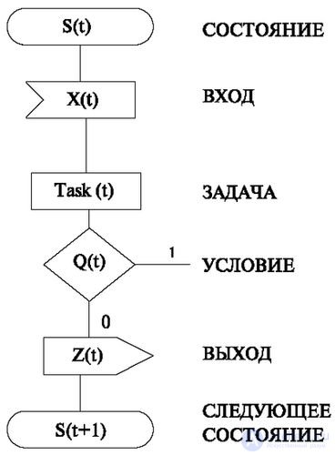
According to the CCITT recommendations, the following notation is used for the image of the algorithms (Fig. 4.3).
When using these symbols there is a small number of natural restrictions.
Note that there are no restrictions on the number of the following TRANSIT operations (TASK, CONDITION, OUTPUT), nor on their order. The above limitations allow one more mapping of the algorithm recorded in the SDL in the form of a correspondence table (Table 4.1) 2 , which maps each pair of INPUT-STATUS sets of actions during the transition.
| Name of operators | S (t) | X (t) | TASK | Q (t) | Z (t) | S (t + 1) |
| Operator Values | s (t) | x (t) | Taks (t) | 0 | z (t) | s (t + 1) |
| one | s (t) | s (t + 1) |
In table 4.1 in the top line in large letters are written the names of the operators of the language SDL, in the second line - their current values.
The names of the operators indicate that this column contains numeric values specifying the numbers of specific actions. To do this, enter the appropriate numbering that displays the possible values of the operators.
s (t) - indicates the number of the state in which the process is located. For example, table 4.2 shows an example of operator STANDING numbering.
This table is either compiled by state numbering in the finished algorithm, or set by the development manager (for limiting names and the number of states), or accumulated, monitored, replenished, and proposed by individual values by the automation system.
| State name | Numeric value |
|---|---|
| Free | one |
| Waiting for the first digit | 2 |
| Waiting for hang up | 3 |
x (t) - indicates the number of the input signal that initiates the transition. For example, table 4.3 shows an example of the numbering of the operator INPUT.
| Login Name | Numeric value |
|---|---|
| The subscriber picked up the phone | one |
| The subscriber has hung up | 2 |
The INPUT operator, before it enters the main processing algorithm, is performed by the "scan" module (object).
Q (t) - indicates the number of CONDITIONS. For numbering the condition, the indices are used under the letter Q. Table 4.5 shows an example of the numbering of CONDITIONS (one CONDITION is displayed in the table).
| Condition name | Numeric value |
|---|---|
| Free Prt Found | Q1 YES-0
NO-1 |
z (t) - indicates the number of the output signal, to surrounding devices or algorithms. task (t) - specifies the number of the TASK.
When numbering these operators, several comments should be made. As shown in the previous sections (3.1-3.9), many of these functions are performed by algorithmic modules and, in the terminology of the object-oriented approach, by objects. Accordingly, the modules have their own behavior and interfaces, shown earlier.
For example, OUTPUT, indicating the on and off of acoustic signals, is performed by the command transmission module. This module (object) according to the ideology of the object-oriented approach has its own interface. Therefore, when describing an interface, the numbering of sequences of commands is indicated, which may be specific values of the OUTPUT operator. Usually they are multi-valued. For example, a number consisting of two parts is used: the first contains the number of the device (object) that must execute the sequence of commands, and the second part (through a dot) indicates the specific sequence of commands.
Table 4.6 shows an example of OUTPUT numbering. This table assumes that the numbering of the Acoustic Connection object is associated with number 3 (the first part of the OUTPUT number) and it can form two command sequences (the second part of the OUTPUT number) - “on” or “off”. These actions are reflected respectively by the numbers 1 and 2 in the second part of the number.
The signal number EXIT with the name "turn on timer 20 seconds" assumes that the timer is object number 4 (the first part of the number), and the action "turn on 20 seconds" has number 1.
Once again, we recall that the assignment of these numbers is done arbitrarily according to a ready-made algorithm, either by the manager or by the automation system, but subsequently strictly adhered to. Particular importance is attached to the resolution, prohibition or restriction of synonyms. For example, the term "include" may have synonyms "activate", "run", etc. For a tabular algorithm, the execution of synonyms operators is possible, but it is better to fulfill the commandment "Do not multiply entities unnecessarily", since polysemy can lead to difficulties in understanding by the developer or user.
| State name | Numeric value |
|---|---|
| Turn on busy tone | 3.1 |
| Disable busy tone | 3.2 |
| Enable acoustic station response | 3.3 |
| Enable timer | 4.1 |
The TASK operator is also performed by modules that, like OUTPUTS, have their own interfaces. The principle of number assignment is the same as for OUTPUTS.
For example, when performing the TASK named “find a free receiver”, you must indicate that it is intended for the intermediate path search module (it also searches for free devices) and the action number inside this module.
Table 4.7 shows an example of numbering TASK. In this case, the assigned number 2.1 indicates that the "intermediate path search" module (object) has number 2 (the first part of the operator number), and the "find a free MCSP" action (Multi-Frequency Number Receiver) has the number 1.
| State name | Numeric value |
|---|---|
| Find a free MCHPP | 2.1 |
Note that when a message is transmitted to an object, the operator's number is accompanied by the necessary information, which was considered when describing individual algorithms. These data are indicated in the figures (Fig. 3.2, 3.5, 3.8, 3.11, 3.17, 3.23) in the form of some inputs.
Returning to the correspondence table, we can say that to describe the operation of a large device, for example, a station, the table should include all the transitions of the algorithm, which is hundreds of thousands of lines. This implies the availability of software support for minimizing tables, minimizing their storage in memory, search and correction. However, the advantage of the tabular approach is that these operations are in no way connected with the features of the algorithm itself and have all the properties of software for distributed programming systems. That is, the interaction elements are hidden from the user: the location of the object, the implementation of the object, the mechanism of communication with the object.
Another advantage is the direct transition from the algorithm to the program. This enables automation and fast implementation, which allows application developers to focus on applications and not worry about the problems of distributed system programming of the lower level.
Consider an example of a table mapping algorithm. In fig. 4.4 shows a simple algorithm performed by the automaton approach and written using the SDL language.
The same algorithm is displayed using the correspondence table (table 4.8), in which the numbering of the operators is used, given by tables 4.2-4.7.
| Line number | S (t) | x (t) | TASK1 (t) | Q 1 | TASK2 (t) | TASK3 (t) | S (t + 1) |
|---|---|---|---|---|---|---|---|
| one | one | one | 2.1 | one | 3.3 | 4.1 | 2 |
| 2 | 0 | 3.1 | 3 | ||||
| 3 | 2 | 3.2 | one |
Let's try to describe the operation of the algorithm in accordance with table 4.8.
First line. In the state S (t) = 1 (free), the input signal x = 1 is received (the subscriber picked up the handset). This INPUT-INPUT-CONDITION pair causes a TRANSIT, which includes the following actions.
Task - Task2 (t) = 2.1. Find a free MCHPP.
Suppose that the value obtained is Q 1 = 1 - the free MCSP is found, then we continue the actions in the first line.
Turn on the request for the transfer of commands by the device connecting acoustic signals task2 = 3.3.
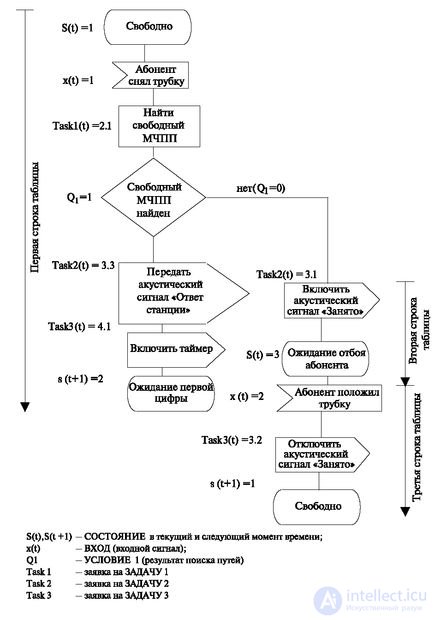
We transmit a signal to activate a timer equal to 20 seconds to wait for dialing (task3 = 4.1).
We complete the transition by setting the state s (t) = 2.
Second line If, after checking the condition, Q 1 = 0 - no free MCSP was found, then the following actions are taken:
Task2 = 3.1 (the acoustic signal is "busy").
Task3 is not executed, because it contains a dash (-).
At the end of the line, the state is set to s (t) = 3.
The third (last) line starts with the state s (t) = 3.
When the input signal x (t) = 2 ("subscriber hung up"), a transition is performed that contains the following actions (we remind: the actions indicated by a dash are not performed, and the next column of this line should be processed):
Task 3 = 3.2 ("mute the acoustic signal").
Set the state s (t) = 1 (free).
The above description shows that there is an inverse match, that is, the table can be uniquely translated into an SDL algorithm.
Moreover, the language at the first stage of implementation had a text version, which was not developed. In the tabular approach, it can be used to automate one of the most “boring” works - the compilation of a description of the algorithm.
A table row can be matched with text that is filled in according to parameters inserted into the table. The result is a description of the operation of the algorithm.
For example, for the row of table 4.8, the following text may be presented:
"If the system is in a state ........ and a signal has arrived ....... then it is executed, ....... the condition is checked .... If as a result of the test ... .., then ... ... ... acoustic ... .. timer ... .... And the system goes into state ...
All missing words are restored using the parameters of the table and the values specified in the dictionary.

Comments
To leave a comment
Telecommunication Services and Devices
Terms: Telecommunication Services and Devices