Lecture
Abstract: The systems of asynchronous and synchronous transmission, the principles of the formation of acoustic signals are considered. Power systems and current distribution network principles are shown.
It should be noted that the synchronization problem appeared with the introduction of a clock generator at the station. As we have seen, all the time channels were divided in time due to the bars. At the same time, it is necessary to periodically mark the beginning of frames, cycles, etc.
It should be noted that until recently, synchronization problems in electromechanical PBXs did not exist. In the first electronic PBXs, the "request-response" transmission method was used, which did not require a clock generator. This method is illustrated in fig. 6.1.
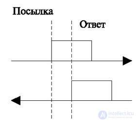
If you need to send a single pulse, the system sends a high level signal (leading edge) to the line. After receiving the neighboring station responds with a confirmation, it causes the termination of the sending signal in the forward direction. This method requires a forward and reverse path, but it has the advantage of not needing clocks and there is no such serious problem as synchronization. At the time of the digital transmission, the requirement for a return path was unacceptable, so all digital technology went the way of installing the clock generators. The method is mentioned for completeness and as a further perspective for the development of digital technology.
As already mentioned above, for the normal operation of digital devices in the network, it is necessary to establish uniform moments of counting and numbering of cycles [4].
Digital technology has two ways to set up this time base:
The first method of transmission is associated with each of the transmitted messages.
The beginning of the message is marked by a special group of characters, called "start", and they also complete the message, so the combination is called "start-stop".
From the moment of accepting the start-stop mark, the system starts receiving information, and the generators should not diverge during the largest message. Asynchronous system is especially attractive for cases of low load and short messages. In this case, the stations can have low accuracy generators that can maintain the stability of the process of reception and transmission for a short period of time.
Synchronous systems are designed for large message flows or continuous messaging (sometimes empty, filling in pauses).
For proper exchange between the two stations, there must be a perfect coincidence of the frequencies of the phases of the generators at both stations. In real equipment, generators have tolerances for the generated frequency. Currently there are generators, the pulse generation frequency of which has an accuracy of 10-6, 10-9. Fig. 6.2 illustrates the process that occurs when a pulse frequency mismatch.
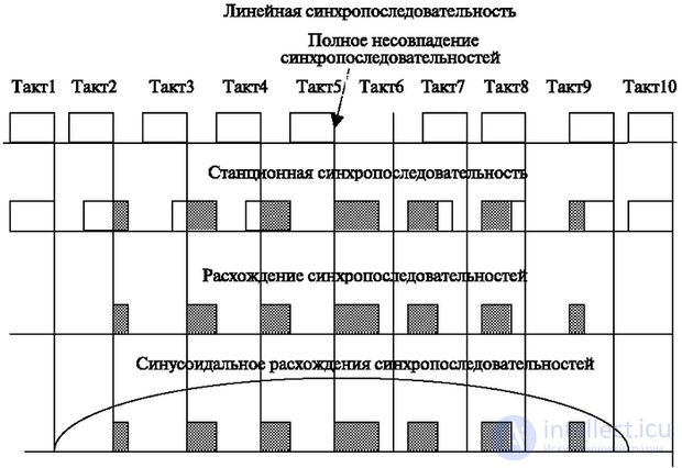
In fig. 6.2 shows the sequence of pulses of the local station generator. Below is a series of pulses arriving along a line and representing coded information (hereinafter, we will call it “linear sequence”). For simplicity, it is shown that information pulses are without intervals (gaps). In real hardware, the pause between pulses depends on the source codes and linear coding. Suppose that at the initial moment of time the leading edges of the pulses of the local generator and the linear sequence coincide. In the figure, areas of the discrepancy between linear and local generator pulses are indicated in gray. At the beginning, they coincide almost completely (lengthening or shortening of pulses of the order of 10-6 or the same discrepancy between intervals is insignificant).
Next, we consider the 2nd moment when, due to the difference in frequency (or the same difference in pulse durations and intervals), there is an accumulated shift between the phase of the linear pulse sequence and the sequence of pulses that are generated by the local generator. As we can see, the area of coincidence has decreased. At the 3rd time point, the area has decreased even more. Such a decrease may cause the pulse not to be accepted, and this will further lead to failure at other higher levels (for example, at the frame synchronization level). At the 4th moment, the area of coincidence remains small. When this happens, a new phenomenon occurs: a complete mismatch (the 5th moment) or a coincidence with the next pulse of the sequence of pulses of the local clock generator (the coincidence on the tail of the 6th moment). Next, an increase in the area of coincidence with the subsequent impulse, and then full coincidence again occurs. Thus, there is a change in the area of coincidence, or, as they say, "jitter" of the phase, which is understood to mean the phase discrepancy between the local clock generator and the linear sequence.
In fig. 6.2 shows the area of coincidence of the pulses of the considered sequences. In the ideal case (when the discrepancy between the parameters of the two frequencies is stable and is determined only by the accuracy of the generators), the magnitude of this area changes periodically. In this case, coincidences occur at the beginning, then at the end of linear pulses. Therefore, often the change in area is indicated by a sinusoid (Fig. 6.2), indicating an increase and decrease in the area of coincidence, and a sign indicates which of the two sequences is leading. The accumulation of the phase difference with high accuracy of generators and high stability of the transmitting medium occurs rather slowly (day, week, month). Therefore, the period of the sinusoid is quite large.
Allocation of the specified areas of coincidence in real equipment serves as an indicator for mutual adjustment of generators. Using the pulses of the incoming information, a special device (clock pulse selector) determines the frequency of the transmitter generator. This is possible if the transmitter impulses go without interruption (or with a short interruption), for which special coding is used (see "Linear coding" [5]).
In addition to the instability of the generators, there is a divergence of frequencies in various parameters (phases, periods, etc.). The main causes of phase wander are:
The change in the length of the cable line occurs as a result of temperature effects or as a result of atmospheric changes leading to bending of the radio path. At the same time there is a slowdown in distribution, which changes the actual transmission rate. The most significant increase in the path of propagation has satellite channels, where the change in the path can reach up to 300 km, which increases the signal transit time by about 1 ms. The relative change in speed with temperature changes is small, but comparable to the accuracy of the clock generator.
This increases the need for frequency control at the receiving station.
Complicating matters is the fact that wandering is irregular.
The change in propagation velocity is associated with changes in the physical parameters of the line (for example, inductance values and capacitance of lines). These changes are about the same order of magnitude as changing the length of the line. With the radio path, large adjustments are made by the environmental parameters (for example, humidity).
Doppler shifts. This factor is the most significant source of potential instability of the clock frequency that occurs when communicating with moving objects. For example, when the aircraft is moving at a speed of 500 km / h, the instability of the clock frequency can reach 5 x 10 -7 .
The reasons discussed above require mutual frequency adjustment between interacting digital information devices.
There are two types of station generators with auto-tuning. The structural diagram of the first of them is shown in Fig. 6.3.
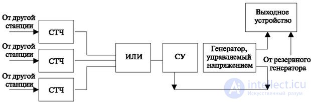
The main device included in its composition is a voltage controlled generator. Clock frequency selectors (TSC) are extracted from the channel-supplied linear sequence of channel clock pulses of the transmitter. These pulses come to a comparison device (SU), which determines the area of coincidence (see Fig. 6.2) and converts (integrates) it into voltage. This voltage is applied to the input of a voltage controlled oscillator that changes the frequency of the local oscillator. The process continues until there is a complete coincidence of the moments of receipt of the clock pulses of the local generator and pulses arriving along the line. In fig. 6.3 it can be seen that the adjustment can be made from several neighboring stations. In this case, the generator is tuned to the arithmetic mean of the frequency.
The second option is shown in Fig. 6.4. It contains a general station pulse generator (JIU), which operates on the clock pulses received from the master oscillator (charger). These pulses come through a trimming device (PU), which receives pulses from the master oscillator, generates the necessary pulse sequences at the outputs with the necessary frequency by dividing them and connects them to the specified devices.
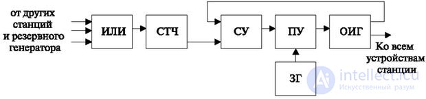
The frequency of the master oscillator is always higher than any other of the set of frequencies at the station. For example, at the frequency required to control the digital path, a frequency of 2.048 MHz is required and to control the control computing complex — 4.096 MHz. Then the frequency of the master oscillator is chosen to be equal to 8.192 MHz, and the necessary pulse sequences of the desired frequency are obtained by dividing the frequency of the oscillator. Recall that the divider is usually a counting circuit - a binary counter that operates on pulses of the master oscillator. This counter has a number of outputs equal to the number of digits. Then each subsequent output produces pulses with a frequency two times lower than the previous one. (Compare the change of binary digits in consecutive binary numbers).
On command, the comparing device can either count another impulse additionally or delay the counting in any digit or skip it. Thus, the phase adjustment of the general station generator occurs.
We note some special moments in the work of generators.
First, the clock selectors work from the fronts of pulses arriving along the line, and in the event of a large interruption in the arrival of such pulse signals, the selectors cannot provide information. Therefore, it becomes clear the important role of information coding to ensure a sufficient density of impulses. Secondly, the selector requires a certain signal-to-noise ratio to extract the clock frequency from the linear signals. If the noise level is close to the signal level (low ratio), the selector will not be able to determine the onset of pulses coming from the line, so the receiver frequency will not be adjusted or the correction will be incorrect, which will lead to network disruption.
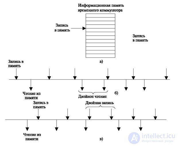
The difference between the incoming frequency values and the local oscillator can be smoothed using "elastic memory". "Elastic memory" (Fig. 6.5a) is a buffer memory for a digital signal, in which recording is made with the line frequency, and reading - with the frequency of the local generator. Elastic memory accumulates information (byte-by-byte), which allows:
With this solution, only short-term generator instabilities can be compensated for, in which the number of transmitted and received bits is limited. If there is a constant shift between the frequency of the pulses arriving along the line and the local generator, the “elastic memory” eventually either overflows or becomes empty.
As a matter of fact, when temporarily switching channels, which we have already mentioned when describing temporal switching, the information memory represents the "elastic memory" and requires a certain ratio between the moments of recording and the moments of reading. If this ratio is violated, the transmitted information is distorted.
When the read cycles are ahead of the write cycles, the same information is read twice ("slippage") (Fig. 6.5b).
In the reverse case, double entry occurs (Fig. 6.5c).
The most dangerous is when the moments of reading and writing for the same information buffer almost coincide. Then instability can lead to the fact that both appeals will periodically change places.
Because of this, "slippage" caused by double readings may follow the "slippage" caused by double entries.
Therefore, it is necessary to introduce a delay between writing and reading (it is symbolically shown in Fig. 6.4a).
The frequency of "slipping" is determined by the difference in the frequency of repetition of the cycle? F. Knowing the accuracy of the generator, it is possible to determine the frequency of "slippage" and vice versa.
In the PCM speech signal with 25 slips, there is a sharp short-term sound - "click". To reduce the impact on speech of these "clicks", the standard of speech quality assurance is defined - 300 "slippings" per hour. This is ensured by the accuracy of the generator 10 -4 .
When transferring data, one “slip” leads to a request and retransmission of information, and consequently, to a decrease in the actual transmission rate.
In addition to synchronization of station generators at the data link level, synchronization of generators of the entire network is necessary.
The principles discussed below are intended to provide station instruments with acoustic and multi-frequency signals. In electromechanical systems, these were hardware devices. In software-controlled systems, these functions are implemented using the following software:
Standard phrases are used for stable messages. For example, when referring to a time service, the standard phrase is pronounced: "Moscow time .... hours ..... minutes". When using cards with prepaid calls, the phrases "Enter the PIN code" or "Sorry, you dialed the wrong PIN code".
Standard messages can be set at the request of the subscriber.
These are roughly the following texts: "Subscriber ... changed the number. Please call the number ....". Sometimes he himself can record them at the station (in addition to his answering machine). These are, for example, the texts "I left, I will be only .... November. Give all messages to your mother. Her phone ..."

Comments
To leave a comment
Telecommunication Services and Devices
Terms: Telecommunication Services and Devices