Lecture
The intermediate paths search algorithm performs one of the mass tasks and is applied when there is a multi-stage switching system at the station. It is intended to find in it a free and accessible call line. The algorithm, the block diagram of which is shown in Fig. 3.17, can search for lines between the following points:
When implementing these operations, the following types of search are used:
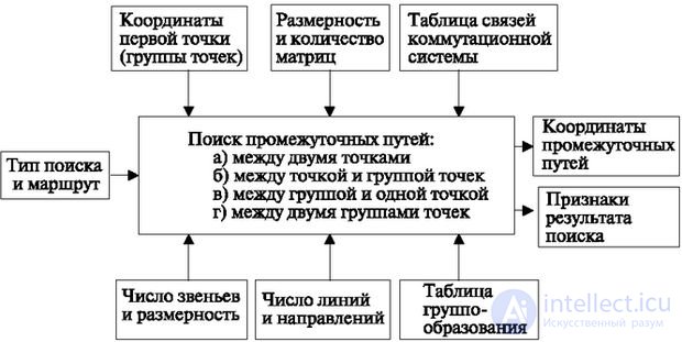
In all software-controlled systems, the considered algorithm performs an action to search for one of all free and available lines between two specified points. This method is called the conditional search "from end to end."
In the application for the operation of the intermediate line search algorithm (Fig. 3.17), the following parameters are set: the data of the address of the first point (or group of points), the type of search and the route. The required type of search can be selected from the list above.
Route selection is necessary when searching is carried out within different blocks. For example, between two points of a subscriber line unit (BAL) for local communication, or between a point and a group of points in a connecting line unit (BSL) for transit communication, etc. The route points to combinations of such a search (BAL - BAL, BAL - BSL etc.). The result of the search for paths contains the coordinates of the intermediate lines (information about the specified endpoints is transferred from the input request): the sign "Path found", and when busy - "Path not found". In addition to these two most common signs, it is possible to include such signs as "The path was found taking into account the category". For example, in cellular networks in the case of priority communication, with a semi-automatic connection from the AMTS.
Recently, systems have been used again in which the search is carried out sequentially along the links of the switching field (for example, System 12). The control features here are that the processor sequentially generates commands containing the specified types of searches.
In addition, modern digital switches can change the relationship between inputs and outputs, and the search can be conducted through a different number of links. Therefore, when generating commands, the number of search type attributes (for example, up to 16) increases, and the search result is generated and transmitted to the processor (software) by the switching field itself. But this does not change the logical content of the process (despite the small difference in the operation process).
To configure the module that implements the search for paths, the following data is necessary:
To search for intermediate lines, arrays of memory are organized, reflecting the various elements of the switching system. As already mentioned, memory arrays are closely related to the equipment, the state of which they display.
In this case, the value of 0 is usually attributed to the state of the line "Busy", and 1 - "Free". In fig. 3.18 depicts an array reflecting the state of the outputs of the matrix connectors of the links A (for the outputs of the link B and the outputs D, the structure of the array is the same).
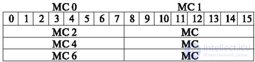
The outputs of the switching system should reflect the state of the connecting lines to other stations and ensure the possibility of redistribution of these lines in different directions. In fig. 3.19a depicts one of the ways to organize memory directions. According to this method, the status of eight lines can be written to each of the 16-bit words. Each line can have four states: free / busy and locked / unlocked. In the memory array, two binary bits are allocated for each line to display these states.
All words reflecting the state of lines in one direction are arranged in one of the subarrays. For all subarrays of direction, an array of directions (Fig. 3.19b) and an array of base addresses are organized, which indicate the beginning and end of the subarray of each direction, including station devices such as dialing receivers, frequency transceivers, etc. Each channel number in the direction is set to correspondence number recorded in the array of positional numbers (block, matrix, output link D).

The general algorithm for searching intermediate paths is shown in Fig. 3.20 for the four-link scheme.
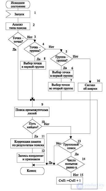
First of all, the application is analyzed and the type of search is determined (operators 3-5). If a type of points is indicated in the type (operator 4), then one point is selected from them (operator 6 or 8), and the search is carried out between two points.
In the future, the search for lines between two points (operator 9). If the line is not found (operator 10), then the search type is checked (operator 13).
If the search is grouped, it is analyzed whether it is possible to make another search attempt with another point in the group. This is possible if the number of attempts did not exceed the maximum specified n – 1 (operator 14). If lines are found, then the state of the intermediate lines is corrected by the search result, the result is generated in the form of the coordinates of the intermediate path and the search result (operators 11 and 12). In all cases, at the OUTPUT of the algorithm, a sign is formed (operator 12) that has the value "Path found" or "Path not found".
The principle of conditional searching consists in the sequential determination of the total vacancy of the sections of paths according to the availability graph, which shows all the available paths between two points. A graph is called series-parallel if any of its two sections are included either in series or in parallel. The four-element grouping scheme without expansion and compression is shown in Fig. 3.21. It contains links, denoted by the letters A, B, C, D, each of which is formed using eight switches. Each switch has eight inputs and eight outputs.
The circles in this figure correspond to the connectors of the links A, B, C, D, and the arcs correspond to the intermediate lines between them. Each arc indicates the state of the line (0 - busy, 1 - free). In the considered column for example, it is shown that the connection from subscriber 0 from link A can pass through 8 connecting lines of link B (in the example, the counting of lines starts from 0 and n 1 = 7); then 8 paths of the next link (in the example, n 1 = n 2 = 7) to the connectors of the C link, etc. This graph is called simply connected, since only one line leads to a specific connector from each connector of the previous link.
The task is to find the paths in the graph between two points marked only by one (free for all links). The search procedure is implemented by a logical multiplication of memory words that reflect the state of the lines forming one path from point to point. Since in some links one output leads to several outputs of the next link, and its state is encoded by one bit, this state usually "multiplies", that is, a new word is formed, where each bit repeats as many times as there is a line in the next link, which are available to this input. So, on fig. 3.21 One of the free intermediate lines of link A is available eight lines of link B. Therefore, its condition (equal to 1) is represented as an eight-bit word 11111111, and the joint freeness of the path from the input of link A to the output of link B is defined as the logical product (conjunction) of this word output word of level B.
To implement the search, two points are set, for example, the number of two subscriber sets, or the number of the subscriber set and direction.
In this case, not only the outward direction can be defined, but also the direction to any block of service kits.
In the algorithm in fig. 3.22 after its launch by the central program, operator 2 allows determining the states of the outputs available to the subscriber set (outputs of the matrix connector of the link A). The next statement, 3, "propagates" this information. This is denoted N AB : = 8 * S AB . After that, the free and accessible intermediate paths are determined along any line between links A and B to any output of link B (operator 4).
Further actions (operators 5 and 6) repeat the previous procedure, but only from the side of the link D. The number of the status byte (S CD ) in the array (M CD ) is determined by the set number (it is either specified in the application or selected from the direction group) .
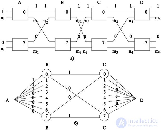
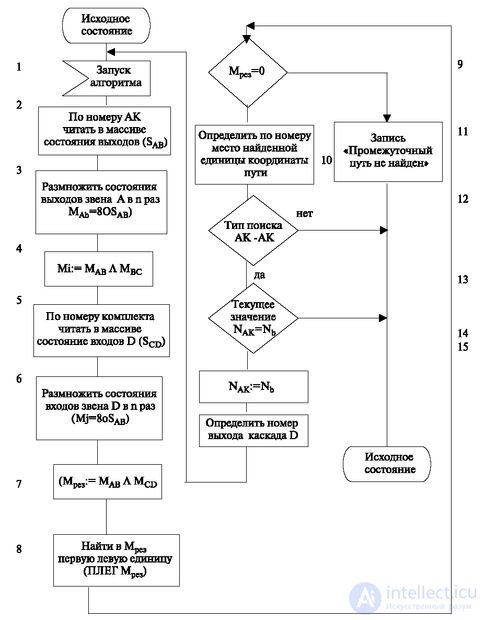
Then the states of this byte logically multiply (operator 6), forming an array (M j ). Next, the operator calculates (operator 7) the result array (Mrez), which determines the lines that are free and accessible from both sides between the two outputs of the link B and the inputs of the link C, for example, from the subscriber set and the output from the station.
After that, the array is analyzed and one of these lines is selected from it. Any of the selected lines is characterized by the presence of a unit in the resulting array.
In the simplest case, this is the search for the first left unit (operator 8). Often used more difficult choice. One of these cases is the selection by the counter, which indicates the beginning of the search.
In this case, the search begins with the unit, the number of which indicates the beginning of the search and is carried out according to the cycle. In fig. Figure 3.22 shows an example of the execution of the intermediate path search algorithm.
At the end of the algorithm is formed (operator 9) one of the signs "Path found" or "Path not found" (Mrez = 0). In the first case, the resulting word is decrypted to form the coordinates of the found intermediate path. For this, the numbers of connectors and their inputs in each matrix of each link are determined by the location of the found unit (operator 10). Figure 3.22 shows the search between the two sets (local communication), so the process is repeated for the second part of the path to the subscriber B (operators 12-13). If the second half of the path is scanned, then the algorithm is completed. If the search is grouped, then in the absence of paths, the end set is changed and the search is repeated. Once again it should be recalled that only the simplest algorithm is considered here. In real stations, space-time switches are currently used, in which the output is represented by group paths of 32 or more channels. Then the edges of the graph are transformed into bundles of lines, and the search is somewhat more complicated. All stations, without exception, use bypass directions, which requires repeated searches in the other direction.
However, despite this, in reality, the simplest principle we have considered only acquires detail, but remains essentially unchanged. When interacting with the central program, it receives one of the above types of requests and uses the memory areas of the central processor. After the search, it places the coordinates of the path found in the memory area of the central process, and if the path is not found, it forms the next state "Path not found" in this area and gives a trigger to re-process the TRANSITION, but with new data.

Comments
To leave a comment
Telecommunication Services and Devices
Terms: Telecommunication Services and Devices