Lecture
In fig. 2.7 shows the spatial switching element at 16 incoming digital paths and 16 outgoing (output) time digital paths each at 32 temporary positions. This scheme consists of 16 connected in parallel at the input of multiplexers, time-controlled information, which comes on the control bus from the address-time memory. One word of temporary memory contains 16x64 bits. Each multiplexer receives 4 bits. They indicate which path should be connected in this multiplexer in this temporary position.
A similar circuit is installed at the receiving end, but with demultiplexers connected. The control principle remains the same.

Spatial switches were widely used in the initial stages of creating digital PBXs. Their main advantage is the low latency of switched information. Currently, due to the increase in the speed of operation of the microcircuits, space-time switching is used almost everywhere.
The principle of implementing a space-time switch using a storage device (Fig. 2.8) is almost the same as for a temporary switch.
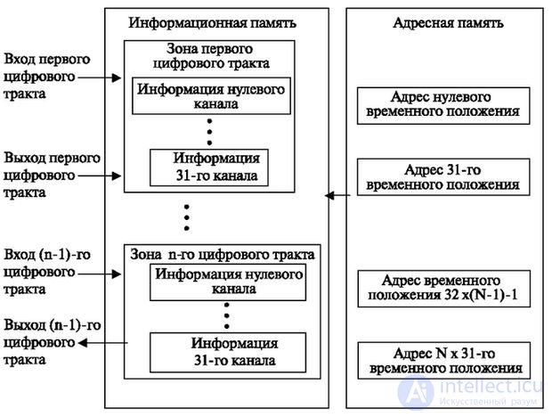
Information memory is set for each digital path. Address memory is installed in a volume equal to the total number of channels of all paths, and controls all paths on the basis of time switching. The total number of channels that can be served by the address memory depends on its speed. The polling time of all channels must be equal to the time of one cycle (frame), i.e. 125 μs = 125x10 -6 s. When the switch operates, two memory accesses occur: first, when the external control device determines the temporary position number of the write address in the memory; the second is when the contents of the control memory corresponding to the time interval is selected as the read address. This time is denoted by t c . Write and read operations must be performed for each time channel (assuming these times are equal). Get the maximum number of channels for a given memory speed:
C = 125 µs / 2t c µs
where a value of 125 µs means a cycle duration in microseconds for a speech signal sampling rate of 8 kHz,
t c - the duration of access to the memory in microseconds.
As an example, suppose that a single call to memory requires 0.5 µs.
Then the number of channels C = 125 channels.
Modern memory has a much smaller cycle of circulation. Therefore, the total number of channels across all digital paths can reach 1024–2048 channels, i.e. 32–64 paths with 32 channels each.
For the organization of spatial-temporal switching on the basis of a storage device, you can multiplex several streams and carry out the switching of this high-speed stream. At the output, you can again divide the stream into several outgoing (Fig. 2.8).
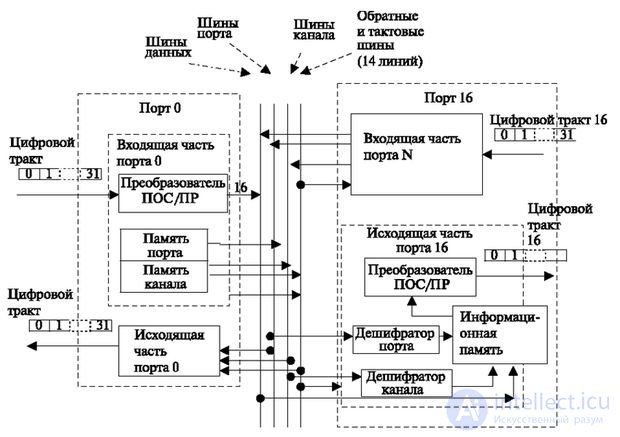
To construct the space-time switches, more complex schemes are used. In fig. 2.9 shows a diagram containing 16 two-way ports with 32 digital channels each. The name "port" means the part of the switching circuit that receives and transmits the digital stream. As seen in fig. 2.9, it is divided into outgoing and incoming parts. The figure shows in detail the incoming part of the 0th path and the outgoing part of the 16th path. The conductivity of the buses connecting these ports is shown in the figure. The data bus trunk contains 16 buses, the port bus has 4 buses, and the bus channel has 5 buses, 14 buses for transmitting return signals and for clock wiring.
Temporary paths are included in the incoming part of the port. Further, the information is accumulated in the serial to parallel converter. Parallel transmission of information allows to reduce the time of exchange between ports by 16 times and thereby increase the number of ports served. Then, in accordance with the time interval, the specified port and channel addresses are read from the address memory.
The control formats for this element are shown in Fig. 2.10.
The format consists of 16 bits, which requires a twofold increase in the transmission rate compared to the byte format, i.e. up to 4096 Kbps.
The first two bits indicate the type of operation mode of the control device of the element (its logic). The first mode (feature 00) characterizes the arrival of a format that does not contain information and corresponds to a free temporary channel. In this case, switching is not performed.
The second mode is the connection establishment mode (feature 01). The work of the element consists in defining and recording information in accordance with the search options recorded in the search type field (in contrast to the name of the format field accepted by developers in telephony, the term “search type” is used).
The following types of search are possible.
For each of the values (0-11, 12-15, 0-7, 8-15, 0-15), a separate search type code is indicated in the format.
In the mode of establishing a connection in accordance with the type of search, the control device of the element determines in memory a port in which there are free channels, and transmits information on the channel search to this port, after which it receives information on the channel number on the return bus and writes it to its own memory. This takes into account the number of remaining channels. If the channel is specified in the format shown in Fig. 2.9b, the information is simply stored in memory.
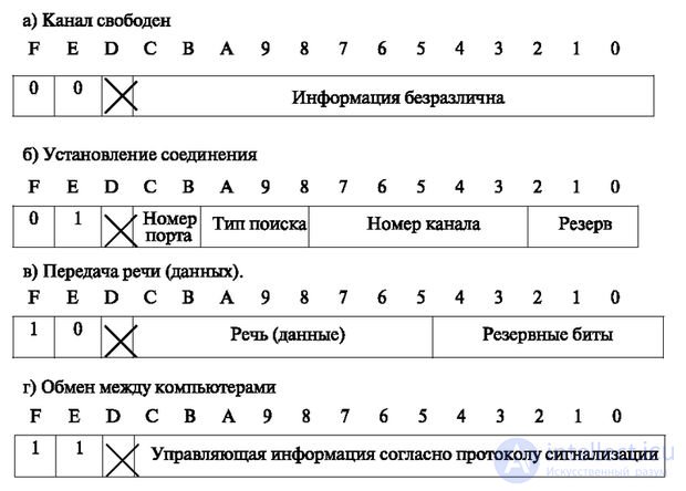
In speech switching mode (data), the format comes in accordance with the temporary position. The address of the port is read from the address memory first, and the channel address in the next cycle.
On the outgoing side of the port, descramblers take the port and channel addresses and write information from the data bus into memory. In the future, this information is read in accordance with the time interval of the outgoing side.
To provide full duplex transmission, pairs of outgoing and incoming ports are installed.
In accordance with the type of search, the element can be configured for various modifications, which are conditionally shown in Fig. 2.10. Note that it is possible to switch information not only from inputs to outputs, but also between any inputs of a single matrix. Information of the zero channel is perceived by the switching element itself to maintain port synchronization with external sources and is transmitted automatically to other zero channels.
Note that at current speeds, the element base of the port can support a path up to 64 channels, which is double the need. Therefore, each port has two inputs and two outputs and is called a “dual port”.
One of the bottlenecks of the system is the central bus, which is switched from 16 ports. For its unloading, multiplexing technique is used, when at the same moment of time each group of buses is used for transmission to different ports (Fig. 2.9).
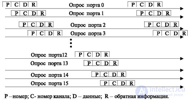
The first is the bus address of the port. The input must decrypt it and open the port to accept the channel address. The port must remain open for accepting information on the next group of tires, and the port information can be removed. At the next moment, this information is transmitted via the bus group of the channel number, and the port address is also transmitted along the group. Then the process is repeated for other groups of tires, as shown in Fig. 2.11. This allows you to not occupy the bus over one time cycle "read - write."
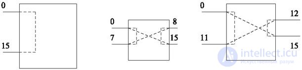
The shown element in accordance with the format (field "type of search) allows using it in three modifications. Unlike the previously considered elements, all modifications are created programmatically, or more precisely by value, in the search type field. These modifications are shown in Fig. 2.12.
The first modification allows switching information from any of the 16 inputs to any of the 16 outputs (search type "any channel Q to any channel P"). This modification will be used to build grouping on the link D.
The second modification divides the ports into input (numbers 0-7) and output (numbers 8-15). Switching is performed mainly from the input port to the output one, but switching between input ports (output ports) is possible. Search type - any channel in ports 0-7 or with any port 0-15. This modification will be further used to build grouping on links B and C.
The third modification makes it possible to carry out concentration and allows you to switch 12 input ports from 0 to 11th with 4 output ports from 12-15 and vice versa. Search type - any channel with any channel in ports from 0-11. Switching between input (output) ports is also possible. This modification will be used in the future to build grouping on link A. The formats of control commands are shown in Fig. 2.10.
Matrix modifications are shown in Fig. 2.12.

Comments
To leave a comment
Telecommunication Services and Devices
Terms: Telecommunication Services and Devices