Lecture
Consider the procedures for the exchange of signals at the user subsystem level [34] - Fig. 5.4-5.6. In many respects, they resemble the procedures already considered for stations of previous generations, both in terms of the signal composition (partially shown in Table 5.3) and the exchange order. Figure 5.4 shows the procedure for exchanging signals when establishing a connection between digital stations of the same type with ACS.
When a Lesson signal is received from the subscriber terminal, which contains the digital information necessary to establish a connection, the outgoing PBX-A analyzes this information and selects the route.
This forms the initial address message (IAM - table 5.3). This signal is an analogue of the "occupation" signal under the old exchange systems. But, taking advantage of the ACS system, it carries much more information.
In particular, it contains the number of the called subscriber. In addition, it carries the requirements for the network, the transmission medium, and the procedures. The structure and content of its format will be discussed in more detail below. Transit PBX-B receives the initial message (IAM), analyzes the information contained in them and determines the further route to the incoming PBX-B. It also connects the reverse link to PBX-A so that Subscriber A can receive the tone signals that may come in the process of establishing a connection from the network elements. Next, turn on the path to the incoming PBX-B.
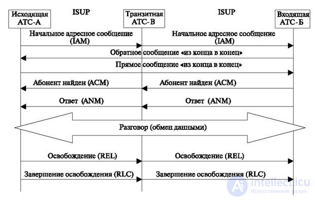
When an initial message (IAM) is received at ATC-B of the called subscriber number, it is determined whether additional information is required from ATC-B about subscriber A. If this is required, a “end-to-end” message is sent (which is indicated in the fixed mandatory part of the message) . Messages of this type are not analyzed by the transit station ("transparent transmission"). The outgoing station provides relevant information by sending an end-to-end response message.
After receiving the necessary information of the incoming ATS-B, the called subscriber is informed about the incoming call, and the message “A subscriber is defined” (ACM) is transmitted from the incoming ATS-B to the transit ATS-B. This signal is equivalent to the reverse signal on the coordinate PBX on the state of subscriber B ("free", "busy", "busy with long-distance connection"). At the same time, there is a lot of other information that expands the possibilities of service. The complete address acceptance message is then transmitted to the outgoing PBX-A, which indicates successful routing and allows you to delete the routing information associated with the connection from memory.
When the called subscriber answers the call, the incoming ATS-B connects the conversational path and sends a response message to the transit station (ANM message), which, in turn, forwards the response message to the outgoing PBX-A station. When receiving the message "Answer the subscriber," the outgoing station sends the path in the forward direction. Thus, the calling and called party connections are established, the call is charged and the call or data transfer is performed.
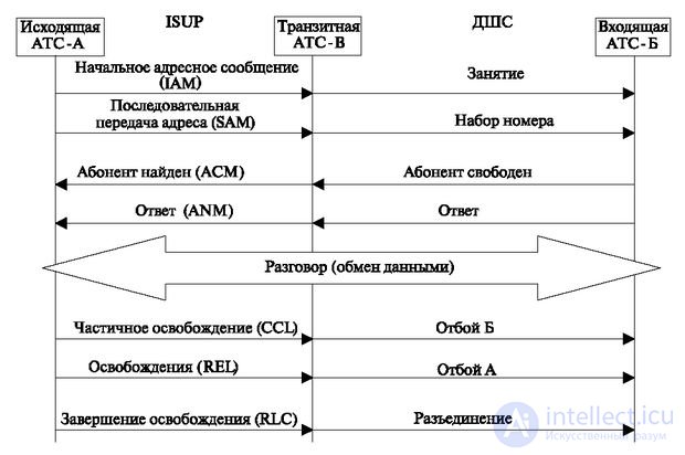
Currently, a one-way call-off system is adopted, when any of the subscribers (called or calling) can initiate a disconnect. In previous systems, where a call delay was required to detect a malicious call, other end-of-call systems were implemented: for example, only from subscriber B (called subscriber) or two-way failure. This requires an additional exchange, which is shown in Fig. 5.5 and 5.6, where the diagram of signal exchange with the systems of the previous generation is shown.
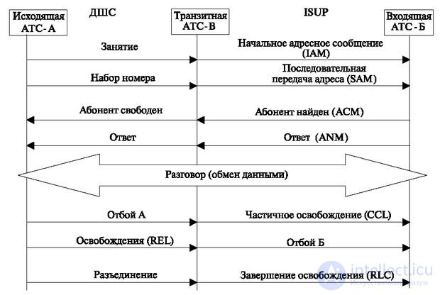
The procedures shown in this figure differ from those already discussed above in that the number is transmitted in parts, so the sequence number digit (SAM) command is used. When the subscriber A is released, a partial release signal (CCL) is transmitted. In response, a "busy" tone is sent to subscriber B and a message about the suspension of the connection until the subscriber B is released. With the decrease in the number of stations of outdated systems in the network, this procedure should be used less and less.
Signal information is transmitted between signaling points as variable-length messages, called signal units. Recall that there are three types of signal units:
The type of signal unit is determined by the LI indicator (Length Indicator), which indicates the length of the field containing useful information;
The structure of the signal units is shown in Fig. 5.7.
Each of the signal unit fields shown in the figure will be discussed further. Basic signaling information is contained in the SIF signaling information field.
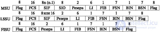
Types of signal units:
In fig. Figure 5.8 shows the message structure of the ISUP subsystem corresponding to Recommendation ITU - T Q.763. As can be seen from the figure, the message is divided into a common part - a label intended for routing - and the following three parts:
Mandatory fixed parameters are always included in messages of this type and have a fixed length. The position and length of the parameters are uniquely determined by the type of message.
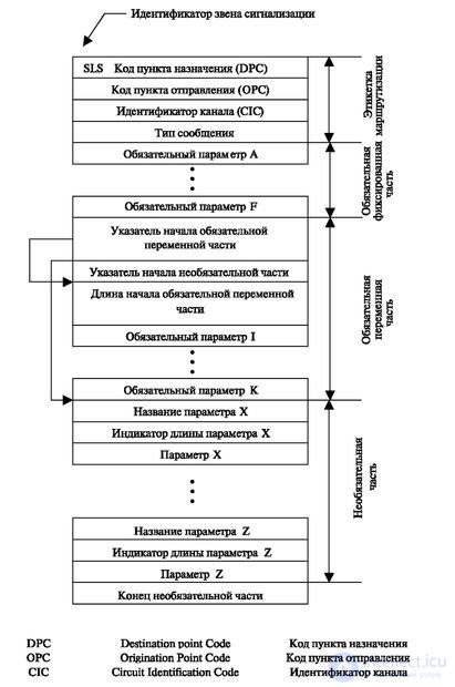
Required variable parameters are required for this type of message and have a variable length. To determine the beginning of each parameter, a special pointer is used, the value of which indicates the beginning of the variable part. The name and length of each parameter is derived from the message type.
Optional parameters may or may not be present in a particular message type. Each optional parameter contains a name (one byte), as in Figure 5.8, for example, the name of the parameter X, and a length indicator (one byte).
Mandatory fixed part contains information about the beginning of the mandatory, variable and optional parts.
Consider the content of fields for specific signals. The initial message (IAM) is shown in table 5.4.
Recall that the transfer to the channel begins with the low byte, that is, the counting of bytes begins on the right side of the figure. The signal information field contains the following components:
The point code determines the location of the alarm point and contains several fields:
The initial message. The structure of the typical SIF field for the IAM message is given in accordance with [34, 35] the fields in table 5.4.
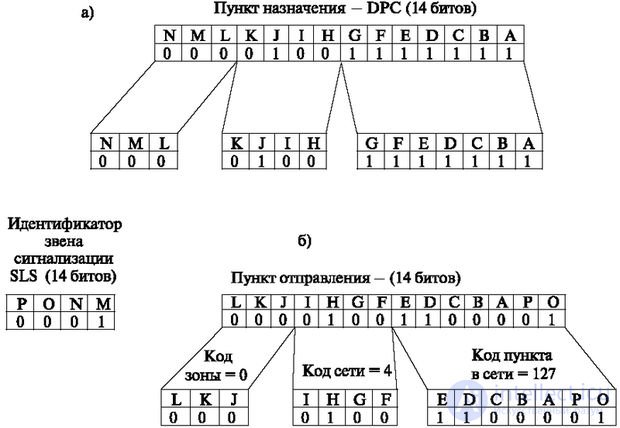
We explain the most difficult part of tabular information - getting the numbers of destinations and departures. In fig. 5.9. The binary codes of the signal information field are displayed (the last column of table 5.4). Bits are arranged in the order of Latin letters. The hexadecimal values of each byte are shown above the sequence.
In fig. 5.9b shows a sequence of 14 bits obtained from the binary information of table 5.4 and showing the destination. It is divided into components: area code, network code, point code in the network. By codes, their decimal values are easily set. Figure 5.9c shows the same splitting sequence for the remaining bits, which show the number of the point of departure.
| Field name | Explanations | Byte and status | & H | Binary code HGFE DCBA PONM LKJI |
|---|---|---|---|---|
| Incoming and outgoing item numbers Signal Beam Selection Identifier | DPC = 0-4-127 OPC = 0-4-97 SLS = 1 | 01 F 02 F 03 F 04 F | 7F 42 98 ten | 0111 1111 0100 0010 1001 1000 0001 0000 |
| Channel number (number of 5 bits) | CICL = 1 | 05 F | 01 | 0000 0001 |
| Digital path number | CICH = 0 | 06 F | 00 | 0000 0000 |
| Message type | Iam | 07 F | 01 | 0000 0001 |
| Media Indicator (NCI - Nature of Connection Indicator) | BA = 00 no satellite channel DC = 00 no channel test required. E = 0 there is no echostender on the outgoing side. HGF = 000 Undefined | 08 F | 00 | 0000 0000 |
| Direct Call Indicator (FCI - Forward Call Indicator) | A = 0 national call CB = 00 - signaling by links D = 1 there is a signal conversion E = 9 no end to end alarm F = 0 no ISDN end-to-end channel HG = 01 ISDN on the entire network does not require ACS I = 0 outgoing call is not an ISDN call PONM LKJ = 0000 000 - not used | 09 F 10 F | 48 00 | 0100 1000 0000 0000 |
| Categories of participants in the connection (CPC - Calling Party's Category) | Category of participants in the connection Subscriber with undefined category HGFE DCBA = 0000 0000 | 11 F | 00 | 0000 0000 |
| Required transmission medium (TRM - Transmission Medium Requirement) | Requires 3.1 kHz transmission medium | 12 F | 03 | 0000 0011 |
| Pointer to Mandatory variable Part (start PMP) | Mandatory variable part starts at 16th byte | 13 F | ten | 0001 010 |
| The length of the mandatory variable part (LI - Length Indicator) | The length of the mandatory variable part is 3 | 14 V | 03 | 0000 0011 |
| Pointer to optional part (POP - Pointer to Optional Part) | Optional part starts at 19th byte | 15 F | 13 | 0001 0011 |
| Called Party Number Indicator (CPN —Called Party Number Indicator) | Called number H = 1 the number of digits is odd GFE DCBA = 000 0010 (local number) | 16 V | 82 | 1000 0010 |
| Network Data (Network Options) | H = 0 allowed the call to the international switching center GFE = 001 - CCITT numbering plan E.164 DCBA = 0000 - reserve | 17 v | ten | 0001 0000 |
| Called Party Number Values | The value of the digit of the called subscriber. The first digit is 2 | 18 v | 02 | 0000 0010 |
| End Optional Parameters | End of optional parameters | 19 o | 00 | 0000 0000 |
Consider the content of the message fields in sequence. The first six bytes are the routing label, which in general was shown earlier in Figure. 5.8.
DPC Destination Codes
In fig. 5.9 shows the specific values of the destination (DPC - Destination Point Code) and the point of departure (OPC - Origination Point Code). It should be noted that information is transmitted from the low-order bit (bit A).
The first field - DPC contains 14 bits of information -
NML KJI HG FE DCBA = 00 0010 0111 1111
It means:
Point of departure (OPC)
The second field contains 14 bits of OPC number information. L KJ IHG F EDCBA PO = 0000 1001 1000 01
The signaling link identifier (SLS) contains 4 bits PONM = 0001 — the signaling link selection indicator indicates the presence of one link in the signal connection and its number (SLS = 1). Working with the SLS tag will be considered further (see "Signaling Network Management").
Digital Channel Number (CICL) field. Two bytes are used to transmit channel identification codes (PONM LKJI HGFE DCBA). The first 5 bits (EDCBA) indicate the number of the talk channel within the digital path. The value in the table indicates that the first channel is used for ACS. Recall that for the PCM-30 system, this parameter is maximum 32.
Digital path number (CICH). The digital path number in the table is 0.
The type of message is determined by its number, for transmission of which one byte is used. The initial message (IAM) is assigned a decimal number 1 (binary value is 0000 0001).
The field of the exchange medium indicator (NCI - Nature of connection Indicator). This field information is one byte.
BA = 00 - no satellite channel. This information indicates the absence of significant delays in the transmission of information due to the presence of satellite channels. Otherwise, it is necessary to rebuild some of the current connection parameters at all sites: for example, increase time-outs, signal exchange. Usually, a network restriction is imposed on the number of link satellites.
DC = 00 - no channel testing required. This information is related to the peculiarity of establishing a connection with common signaling channels. Since the signaling method does not use the information path in the method, the integrity of the information path is not guaranteed after successful connection establishment. Therefore, the information path is periodically tested. This value indicates timeouts.
E = 0 - there is no echo canceller on the outgoing side. An increased level of amplification and a large number of receptacles lead to an echo. The absence of an echo canceller indicates that the characteristics of the line are limited.
HGF = 000 - not defined.
Direct call indicators (FCI - Forward Call Indicator) are placed in two bytes.
In this example:
A = 0 - indicates that the connection is within the country (national call).
CB = 00 - signaling by links, indicates that the "relay" system is used in this area.
D = 1 - warns that in some area it was necessary to carry out signal conversion. This information introduces restrictions on sending return signals;
E = 0 - indicates that there is no means on this network for transmitting information "from end to end";
F = 0 - no end-to-end channel. ISDN warns that there are sections on the network that do not contain an ACS digital channels. In this case, the station must decide in which direction to continue the connection;
HG = 01 - indicates that the use of ACS is optional for this connection (for example, a normal conversational path is established with a bandwidth of 3.1 kHz).
I = 0 - indicates that the outgoing call is not an ISDN call and indicates that it is necessary to change the mode of service - this is a signal about the method of service.
The CPC (Calling Party's Category) Participant Category field provides information about the connection category. This concept when establishing a connection coincides with the category of the subscriber. After the connection is established, it is determined by the categories of incoming and outgoing subscribers.
In this case, the value of the HGFE bits DCBA = 0000 0000 indicates that the connection category is not defined.
Required transmission medium TMR - Transmission Medium Requirement. It indicates the desired channel speed resource. Channels with a bandwidth of 3.1 kHz, or 7.2 kHz, or digital channels with a speed of 64 kbit / s can be used for ISDN. The example indicates that a 3.1 kHz telephone channel is required.
Pointer to Mandatory Variable Part. It consists of pointers to the parameters of the mandatory part. In this case, it is indicated that the mandatory part begins with the 16th byte (the counting is from the last byte of the pointer).
Pointer to optional variable part (POP - Point to Optional Part). In this case, it indicates that the optional variable part consists of 3 bytes (in table 3 bytes with a V mark).
The length of the mandatory variable part of the LI. A parameter that determines the length of this part in bytes. For this example, the length of the mandatory variable part is 3 (binary number 0000 0011).
Pointer to the optional variable part of the POP (Pointer to Optional Part).
Called Party Number Indicator (CPNI).
H = 1 indicates that the number consists of an odd number of digits (this can be used in the system checking the correctness of the received number).
GFE DCBA = 000 0010 - local number.
Network data
H = 0 - allows access to the International Switching Center.
GFE = 001 - carries information that the transmitted subscriber number is constructed in accordance with the numbering plan adopted by the CCITT (ITU) in recommendation E.164.
Values of dialed numbers numbers (Called Party Number Values). In a homogeneous network, where all stations have ACS, it is possible to transmit all or any part of the digits of the called subscriber number. For this reason, the field "the value of the digits of the number of the called subscriber" is included in the variable mandatory part, since its length depends on the number of transmitted digits. В данном примере предлагается, что связь идет к станции, принимающей каждую цифру отдельно, и значение цифры — 2.
В поле конец необязательной части ( EOP — End Optional Parameters) данной таблицы указывается на отсутствие опциональных (необязательных) параметров.
Рассмотрим второй сигнал. В случае, если цифры надо передать частями, как это было проиллюстрировано в приведенных выше примерах, применяется сообщение "последовательная передача адреса" ( SAM — Subsequent Address), оно приведено в таблице 5.5.
Информация, содержащаяся в указанных выше полях, уже рассматривалась в первоначальном сообщении ( IAM )
Следующее сообщение уже применялось при описании процедуры установления соединения: это "Адрес завершен" ( ACM — Address Complete Message). Его структура приведена в таблице 5.6.
In this message from the new fields, you can explain the BCI field - the callback field.
BA = 10 indicates subscriber category (whether the outgoing subscriber should pay for connection services or not).
| Field name | Explanations | Byte and status | & H | Binary code HGFE DCBA PONM LKJI |
|---|---|---|---|---|
| Channel number (number of 5 bits) | CICL = 1 | 05 F | 01 | 0000 0001 |
| Digital path number | CICH = 0 | 06 F | 00 | 0000 0000 |
| Message type | SAM | 07 F | 02 | 0000 0010 |
| Pointer to Mandatory variable Part (start PMP) | Mandatory variable part starts at 10th byte | 08 F | 0A | 0000 1010 |
| Pointer to optional part (POP - Pointer to Optional Part) | Optional part starts at 14th byte | 09 F | 0E | 0000 1110 |
| Длина обязательной переменной части (LI — Length Indicator) | Длина обязательной переменной части - 3 байта | 10 V | 03 | 0000 0011 |
| Номер вызванного абонента (CPNI — Called Party Number Indicator) | Номер вызванного абонента содержит H=1 - число цифр нечетное GFE DCBA = 000 0010 (номер местный) | 11 V | 82 | 1000 0010 |
| Сетевые данные (Network Options) | H=0 - разрешен вызов на международный центр коммутации GFE =001 — план нумерации МККТТ E.164 DCBA = 0000 — резерв | 12 V | ten | 0001 0000 |
| Значение цифры вызванного абонента (Called Party Number Values) | Цифра равна 7 | 13 V | 07 | 0000 0111 |
| Конец необязательной части параметров (End Optional Parameters) | Конец необязательной части параметров | 14 O | 00 | 0000 0000 |
| Наименование поля | Explanations | Байт и статус | &H | Двоичный код HGFE DCBA PONM LKJI |
|---|---|---|---|---|
| Номер разговорного канала =1 | CICL = 1 | 05 F | 01 | 0000 0001 |
| Digital path number | CICH = 0 | 06 F | 00 | 0000 0000 |
| Message type | ACM | 07 F | 06 | 0000 0110 |
| Pointer to optional part (POP - Pointer to Optional Part) | Pointer to the optional part of the 11th byte | 08 F | 0B | 0000 1011 |
| BCI - Backward Call Indicator) | BA = 10 - payment is made by subscriber A DC = 01 - hold user A FE = 01 - ordinary subscriber GH = 00 - signaling by links I = 0 no signaling conversion J = 0 display possible K = 1 is used through ISDN-channel M = 1 there is no echostender on the incoming side PO = 00 - no indication | 09 F 10 F | sixteen sixteen | 0001 0110 0001 0110 |
| End Optional Parameters | End of optional parameters | 11 o | 00 | 0000 0000 |
DC reports the status of the incoming subscriber (free, busy, busy with long-distance connection, blocked, number changed, etc.).
FE дает информацию о типе абонента (обыкновенный абонент, гостиничный и т.п.). Значения остальных битов уже рассматривались при описании прямого индикатора соединения ( FCI ) в формате первоначального сообщения ( IAM ).
HG=00 — сигнализация по звеньям.
I=0 — нет конвертирования сигнализации. Показывает, что информация на всем пути не преобразуется в другой вид.
J=0 — возможна индикация " из конца в конец".
K=1 используется сквозной ISDN-канал. Указывает, что сеть имеет участки, которые обладают ресурсами (цифровыми каналами, ОКС и т. п.) для установления сквозного ISDN-соединения.
M=1 — нет эхозаградителя на входящей стороне. Повышенный уровень усиления и большое число переприемных участков приводит к появлению эха. Отсутствие эхозаградителя хотя бы на одной стороне указывает на ограничение характеристик линии.
Следующее сообщение Ответ абонента (ANM) в данном примере (таблица 5.7) содержит только одно содержательное поле — "Тип сообщения".
| Наименование поля | Explanations | Байт и статус | &H | Двоичный код HGFE DCBA PONM LKJI |
|---|---|---|---|---|
| Номер разговорного канала =1 | CICL=1 | 05 F | 01 | 0000 0001 |
| Номер цифрового тракта | CICH=0 | 06 F | 00 | 0000 0000 |
| Тип сообщения | ANM | 07 F | 09 | 0000 1001 |
| Указатель начала необязательной части (POP — Pointer to Optional Part) | Указатель начала необязательной части с 9-го байта | 08 F | 09 | 0000 1001 |
| Конец необязательных параметров (End Optional Parameters) | Конец необязательных параметров | 09 O | 00 | 0000 0000 |
Сообщение приостановки соединения ( SUS — Suspend). Это сообщение отображено в таблице 5.8 и имеет только одну строку, которую мы не рассматривали ранее. Это индикатор прекращения, который указывает тип приостановленного соединения. Этот признак определяет алгоритм обработки сообщения, поскольку есть типы сообщений, которые не допускают приостановки или ограничивают ее длительность. В данном примере указано, что приостановлено соединение абонента ISDN.
| Наименование поля | Explanations | Байт и статус | &H | Двоичный код HGFE DCBA PONM LKJI |
|---|---|---|---|---|
| Номер разговорного канала =1 | CICL=1 | 05 F | 01 | 0000 0001 |
| Номер цифрового тракта | CICH=0 | 06 F | 00 | 0000 0000 |
| Тип сообщения | SUS | 07 F | 0D | 0000 1101 |
| Указатель начала необязательной части (POP — Pointer to Optional Part) | с 9-го байта | 08 F | 09 | 0000 1001 |
| Индикатор прекращения (Suspend Indicator) | A=0 — инициализация абонента ISDN HGFE DCB=0000 000 — не используются | 09 F | 00 | 0000 0000 |
| Конец необязательных параметров (End Optional Parameters) | Конец необязательных параметров | 10 O | 00 | 0000 0000 |
Сообщение возобновление соединения RES (Resume). Это сообщение (таблица 5.9) отменяет приостановку соединения. Его строки имеют то же назначение, что и у предыдущего сообщения.
Сообщение освобождения REL (Release). Передается в случае, когда входящая станция может быть освобождена. Это сообщение, однако, не является признаком полного освобождения всего оборудования, участвующего в соединении. Процесс разъединения определяется принятой системой отбоя.
Особенность этого сообщения состоит в том, что обязательная переменная часть строго разбивается на байты (октеты), конец каждого октета указывается единицей в последнем бите (H-1). Пример использования полей этого сообщения приведен в таблице 5.10.
| Наименование поля | Explanations | Байт и статус | &H | Двоичный код HGFE DCBA PONM LKJI |
|---|---|---|---|---|
| Номер разговорного канала =1 | CICL=1 | 05 F | 01 | 0000 0001 |
| Номер цифрового тракта | CICH=0 | 06 F | 00 | 0000 0000 |
| Тип сообщения | RES | 07 F | 0E | 0000 0010 |
| Указатель начала необязательной части (POP — Pointer to Optional Part) | Указатель начала необязательной части со 2-го байта | 08 F | 02 | 0000 0010 |
| Индикатор прекращения (Suspend Indicator) | Индикатор прекращения A=0 — инициализация абонента ISDN HGFE DCB=0000 000 — не используются | 09 F | 02 | 0000 0010 |
| Конец необязательных параметров (End Optional Parameters) | Конец необязательных параметров | 10 O | 00 | 0000 0000 |
| Наименование поля | Explanations | Байт и статус | &H | Двоичный код HGFE DCBA PONM LKJI |
|---|---|---|---|---|
| Номер разговорного канала =1 | CICL=1 | 05 F | 01 | 0000 0001 |
| Номер цифрового тракта | CICH=0 | 06 F | 00 | 0000 0000 |
| Тип сообщения | SAM | 07 F | 0C | 0000 1100 |
| Указатель начала обязательной переменной части (PMP — Pointer to Mandatory variable Part) | Указатель начала обязательной переменной части с 10-го байта | 08 F | 0A | 0000 1010 |
| POP — Pointer to Optional Part | Указатель начала необязательной части с 14-го байта | 09 F | 05 | 0000 1110 |
| Длина обязательной переменной части (LI — Length Indicator MVP) | Длина обязательной переменной части | 10 V | 03 | 0000 0011 |
| CAI — Call Indicator | Номер вызванного абонента H=1 - октет закончен GF=00 - стандарт кодирования МККТТ E= не используется DCBA = 0000 - отбой инициирован абонентом | 11 V | 80 | 1000 0000 |
| Рекомендации МСЭ-МККТТ (Recommendation ITU CCIT | Рекомендации МККТТ H=1 - октет закончен GFE DCBA = 0000 0000 МККТТ Q.931 | 12 V | 80 | 1000 0000 |
| Признаки действия (Cause value) | Признаки действия H=1 - октет закончен GFE=001 - типовое событие DCBA = 0000 - нормальное разъединение | 13 V | 90 | 1001 0000 |
| Конец необязательных параметров (End Optional Parameters) | Конец необязательных параметров | 14 O | 00 | 0000 0000 |
Поле информации для оплаты. При отбое абонента — инициатора соединения необходимо подготовить информацию для оплаты. Поэтому в битах GF передаются признаки оплаты в соответствии с рекомендациями ITU. Биты DCBA указывают, что отбой инициализирован абонентом, а не устройствами сети.
Поле рекомендации ITU. Процедура отбоя должна соответствовать рекомендации ITU Q.931 (I.451), относящейся к основным процессам управления соединением.
Поле признаки действия. Эти признаки в данном случае указывают на то, что соединение нормальное (не аварийное) и должно быть обслужено по стандартному (типовому) алгоритму.
Следующее сообщение — завершение освобождения RLC (Release Complete) — представлено в таблице 5.11. Оно передается при окончании соединения и по ходу установления соединения, порождая процесс окончательного освобождения приборов.
| Наименование поля | Explanations | Байт и статус | &H | Двоичный код HGFE DCBA PONM LKJI |
|---|---|---|---|---|
| Номер разговорного канала =1 | CICL=1 | 05 F | 01 | 0000 0001 |
| Номер цифрового тракта | CICH=0 | 06 F | 00 | 0000 0000 |
| Тип сообщения | RCL | 07 F | ten | 0001 0000 |
| Указатель начала необязательной части (POP — Pointer to Optional Part) | Начало необязательной части с 9-го байта | 08 F | 09 | 0000 1001 |
| End Optional Parameters | Конец опциональных параметров | 09 O | 00 | 0000 0000 |
Сообщение запрос номера абонента (Information Request, INR ) (таблица 5.12). Основная информация этого сообщения содержится в индикаторах запроса информации. Абонентский номер запрашивается в двух случаях:
В первом случае, кроме самого номера, важной информацией является категория тарифа. Она инициируется в соответствии со значениями битов DE.
Во втором случае, кроме номера, важной является информация о необходимости удержать соединение.
| Наименование поля | Explanations | Байт и статус | &H | Двоичный код HGFE DCBA PONM LKJI |
|---|---|---|---|---|
| Номер разговорного канала =1 | CICL=1 | 05 F | 01 | 0000 0001 |
| Номер цифрового тракта | CICH=0 | 06 F | 00 | 0000 0000 |
| Тип сообщения | INR | 07 F | 03 | 0000 0011 |
| Указатель начала необязательной части (POP — Pointer to Optional Part) | Начало необязательной части с 9-го байта | 08 F | 09 | 0000 1001 |
| Индикаторы запроса информации (Information request indicator) | A =1 — запрашивается номер абонента A B=0 — удержание абонента A не требуется C=0 D=1 — запрашивается категория абонента A. E=0 — нет запроса о тарифе GF= 00 — резерв H=1 — запрос о злонамеренном вызове PONM LKJI= 0000 0000 — не используется | 09 F 10 F | 89 00 | 1001 1001 0000 0000 |
| End Optional Parameters |
Message information - INF (table 5.13) - response to the message INR. In the mandatory fixed part, consisting of two bytes (10F, 11F). Indicates the characteristics (indicators) of this information in the table.
The required variable part contains several parameters:
| Field name | Explanations | Byte and status | & H | Binary code HGFE DCBA PONM LKJI |
|---|---|---|---|---|
| Channel number (number of 5 bits) | CICL = 1 | 05 F | 01 | 0000 0001 |
| Digital path number | CICH = 0 | 06 F | 00 | 0000 0000 |
| Message type | INF | 07 F | 04 | 0000 0100 |
| Pointer to Mandatory variable Part (start PMP) | Mandatory variable part starts at 10th byte | 08 F | 0A | 0000 1010 |
| Pointer to optional variable part (POP - Pointer to Optional Part) | Optional variable part starts at 23rd byte | 09 F | 17 | 0010 0111 |
| Information Indicators | BA = 1 - subscriber number A is transmitted C = 0 - retention of subscriber A is not ensured ED = 0 - not used F = 1 - subscriber category A is transmitted G = 0 - no rate information H = 1 - Malicious call request satisfied. PONM LKJI = 000 - not used | 10 F 11 F | A 3 00 | 1010 0011 0000 0000 |
| The name of the parameter - "categories of participants in the connection" (CPC - Calling Party's Category) | Contains member category | 12 v | 05 | 0000 0101 |
| Parameter Length (LI - Length Indicator) | Parameter length - 1 byte | 13 V | 01 | 0000 0001 |
| Priority (Priority) | HGFE DCBA = 00000 1011 - subscriber with priority | 14 V | 0B | 0000 1011 |
| The name of the parameter "number of the caller" (Calling Party Number) | Caller number | 15 V | 0A | 0000 1010 |
| The length of the optional part (LI POP - Length Indicator POP) | Element length - 7 bytes | 16 V | 07 | 0000 0111 |
| Caller Party Number (Calling PartyNumber) | Additional room features H = 1 - an odd number of digits GFE DCBA = 000 0011 - subscriber number | 17 v | 83 | 1000 0011 |
| Network Features (Network Options) | H = 0 - full number GFE = 001 - CCITT numbering plan E.164 DC = 00 - the display of the number of subscriber A is allowed BA = 11 - display provides network | 18 v | 13 | 0001 0011 |
| Called Party Number Values | 1st digit = 2 2nd digit = 5 3rd digit = 4 4th digit = 9 5th digit = 1 6th digit = 1 7th digit = 3 | 19 v 20V 21V 22V | 52 94 eleven 03 | 0010 0101 1001 0100 0001 0001 0011 0000 |
| End Optional Parameters | End of optional parameters | 23 o | 00 | 0000 0000 |
Specific examples of the construction of the SIF field allow us to present the principles of the construction of the basic control signals for establishing the connection.
Next, we will consider issues relating to the second (channel) level of the message transmission subsystem of the ACS, which determines the structure of information transmitted over the link, the procedure for detecting and correcting errors. Then consider the third (network) level, which provides routing and management of the signaling network.
To protect information from shifting in information signals, each signal unit is opened and closed by a flag, which is a sequence 01111110.
The procedure to protect the flag from imitation is to analyze current information. Each byte of the information sequence, which contains 5 units, is padded with zero. Thus, informational bytes exclude the possibility of imitation of a flag (a sequence containing 6 units in a row). At the receiving end, zero, which goes after 5 units, is eliminated and the sequence is restored.
At the level that will be discussed below, the following fields are used:
To detect errors, the principle of division of polynomials (residual code) is used, which has already been considered in detail in previous lectures. Recall that the FSC field is the remainder of dividing mod 2 polynomial, which transmits information to the forming polynomial. At the receiving end, also by dividing, the coincidence of the result with the obtained remainder (or a slightly more complicated algorithm) is checked. If there is a mismatch, a re-request is made.
The error correction procedure is as follows (Fig. 5.10).
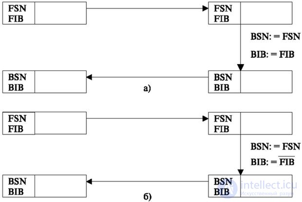
When transmitting information, each signal unit is recorded in the intermediate cyclic memory and stored until a positive acknowledgment is received. The cell number of the record is the same as the direct loop number. Each signal unit includes a forward cyclic number (FSN field) and a direct indication bit (FIB field), the value of this bit is 0 or 1. At the receiving end, if the information is received without distortion, the opposite direction is sent in the BSN and BIB fields. the same information (Fig. 5.10a). Upon receipt of this signal, the transmitting side erases the signal unit from the memory.
If incorrect information is received (Fig. 5.10b), the forward bit of the indication is inverted at the receiving end, and the reverse serial number (BSN) is transmitted in the opposite direction, which coincides with the forward number (FSN), but with the reverse bit (BIB), which is equal to the inversion direct bit. In this case, this signal unit is retransmitted.
For systems with a long delay in transmission, the method of preventive repetition is used. Information that is not positively confirmed after a specified time (usually this is determined by the number of transmitted signal units during the time spent in the information buffer) is transmitted again.
Level 2 also performs the functions of quality control of the exchange path.
For this, errors are counted in a specific time. If the number of errors exceeds a predetermined threshold, level 3 is informed of this for a decision (for example, changing the route).
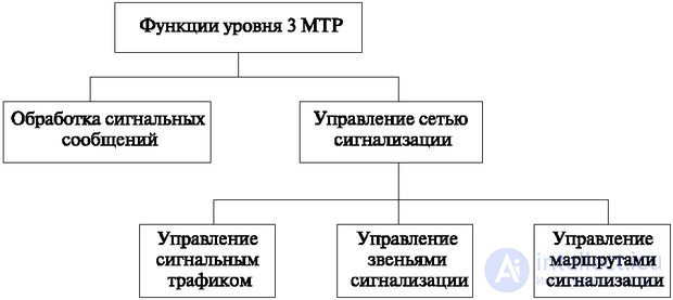
This level performs the following tasks (Fig. 5.11):

Comments
To leave a comment
Telecommunication Services and Devices
Terms: Telecommunication Services and Devices