Lecture
The norms of attenuation distribution are approved by the provisions for network design [14]. In fig. 8.9 shows the attenuation distribution for various options for building urban networks and connection routes.
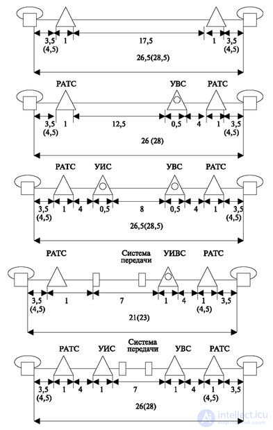
The maximum attenuation between two telephone sets should not exceed 28 dB. In this case, the attenuation of subscriber lines should not exceed 4.5 dB. For a station quadrupole attenuation, the allowable attenuation value is much less: for the RATS, it should not exceed 1 dB per RATS and 0.5 dB at the AIS or UHS during two-wire switching. In four-wire switching, the attenuation of the station quadrupole AIS and UWS is assumed to be 0. The attenuation of the station quadrupole when switching from a two-wire to a four-wire path is 1.0 dB.
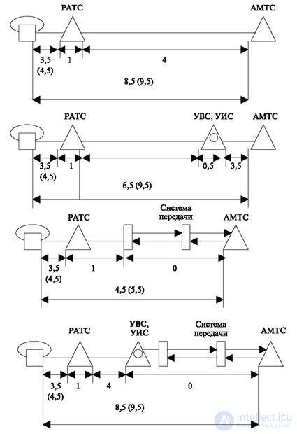
The attenuation distribution on the intrazone network is shown in Fig. 8.10. The attenuation from the telephone to the station, where the transition to the four-wire path (AMTS, UVS, UIS) is carried out, should not exceed 9.5 dB.
The quality of telephone call service on the urban telephone network is determined by the probability of loss or denial of service due to the lack of free and accessible switching devices and channels. The actual or actual losses on calls to the CTA are estimated by the ratio of the number of calls lost per hour (CNN) to the total number of calls received. Estimated loss rates in CNI at various sections of the CTA are used in determining the volumes of equipment in the CTA.
The total estimated losses for GTS subscribers should not exceed 0.030, when communicating with the suburban area and private PBXs - 0.040, and when communicating with PBXs with telephone stations - 0.005.
Estimated loss rates at GTS stations are given in Table 8.1.
| Type of connection or connection | Loss rate in CNN |
|---|---|
| 1. Reception by the subscriber of a station readiness signal to receive dialing | 0,007 |
| 2. Connection between subscribers of one station | 0.020 |
3. An exit on a direct bunch of lines (channels) to functionally isolated group of the switch equipment:
| 0,005 0.001 0,010 0.001 |
| 4. Incoming local connection | 0,010 |
| 5. Incoming long distance | 0,003 |
Connection steps are considered:
1. from the moment of raising the tube;
2 and 3. from the moment of acceptance of the address information sufficient for establishing a connection;
4 and 5. from the moment the call arrived at the station entrance.
The probability of losses includes the probability of occupancy of the inputs of switching equipment, control devices, devices for receiving and transmitting signals, internal blocking of devices of lines and channels. When using detours in the long-distance communication, these norms are used to calculate the number of devices per site of the last choice (between UAK1-UAK1).
In case of losses due to waiting beyond the allowable time, the same standards can be adopted by setting the maximum waiting time.
Earlier, in other courses of lectures, a part of the problem was already considered concerning the work of the station in terms of number analysis and direction selection. Now consider the network aspects of routing. In fig. 8.11 shows the basic concepts that make up the routing definition.

End point This is the goal where the connection is directed.
Endpoint code. This is the number assigned in accordance with the numbering rules.
The following concepts are associated with this code:
When assigning tariffing there may be cases when different substations of one station or PBX of one node belong to different tariff zones. Such requirements may arise due to the specific geographical location of these stations. Requirements are also possible, due to which the substations of different stations can be assigned to one tariff zone.
It should be noted especially that the code of the intelligent network, as a rule, can be marked not by stations, but by services.
When fixing the code, it is also necessary to determine the possible end station responses that may affect the operation of the original station.
These can be the following:
For each endpoint with a code, the time constraints (time-outs) are specified:
Obviously, each of these restrictions must be set to "not set."
Setup completion can also be programmed. Sign of the end of the establishment of the connection can be:
The above actions and restrictions can be set on a combination of a code point and a selected route.
When creating a route, you should define:
It (direction) is characterized by:
Also, the direction characteristic can be a limitation on the type of communication, which is essential when traffic is regulated in case of overload.
It:
This category can be assigned by an operator or system for a specific time.
Combinations of these connections are possible or the introduction of the inverse characteristic "permission to a type of communication", which opens a closed direction for a certain type of communication. In the general case, the direction can be composed of channels that have various of the listed characteristics, but this complicates the programs for managing them.
Channel search method:
Most preferred is the third option.
The first two methods are called "constant priority search".
As is known, damage control is not absolute, that is, it cannot determine (foresee) all network errors, station equipment and environmental behavior. And if one of the channels is damaged or has a degraded quality that is not detected by the control, then the constant priority leads to the LEAST load in an hour of communication failure - since the subscriber chooses the same faulty channel and all the time gets a failure until some other subscriber takes faulty line. Such an event is unlikely with a small load and more likely with a large one. In addition, the constant priority leads to the priority occupation of lines that have a higher priority. This also has its negative consequences (for example, the wear of mechanical elements in the most used devices).

Comments
To leave a comment
Telecommunication Services and Devices
Terms: Telecommunication Services and Devices