Lecture
When considering the issues of this lecture, knowledge of the materials that were presented earlier is necessary. The first thing to remember is the structure of the construction of telephone networks. The second is the ACS alarm system. The third is the routing features, depending on the environment and signaling requirements.
Thus, the ACS network [16, 35, 55] ideally should largely follow the public network. Each of the nodes and each station of a long-distance, zone and local (urban or rural) network must have an alarm system.
However, several circumstances violate the ideal picture. The system of common channels is being implemented on existing networks. Therefore, not all stations are able to interact with this system and not all can be upgraded. All currently installed new stations of the digital system have the ability to install and operate the ACS.
These stations should have the necessary equipment and software. In many cases, stations are started up without these subsystems, they are already installed during operation, which leads to unnecessary costs.
There are circumstances that must be considered when implementing on the network ACS. The first of these is the transition from the old alarm system to the new one and the ways of their coordination.
There are two ways to move networks to new systems. The first is the "island" method, when separate parts of the network are created that have new equipment (in this case, the signaling system OKS). The second system - the overlay system - is that the new equipment is installed geographically close to the already existing one.
In this case, allocated places and equipment for their interaction. In both cases, network heterogeneity causes problems with docking and special routing, taking into account the environment that was considered earlier.
The second circumstance is that the system of the connected ACS is not always economically justified or it cannot be strictly implemented, given the emergency situations, so there is a need to create a quasi-connected network. In this case, the ACS network begins to acquire a character distinct from the public network that it accompanies.
From the point of view of the ACS network, signaling points (SP - Signaling Point) and signaling transit points (STP - Signaling Transfer Point) are distinguished. Consider the organization of the network ACS on specific networks.
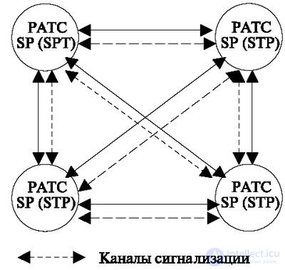
Organization of ACS is possible only if there is a digital system in the city of the PBX and with an unregistered network (Fig. 9.3). The network shown in the figure shows that on a network of this kind all digital stations are connected by bundles of Separate Signaling Channels, i.e. work on a connected system is implied. The quasi-bound system is used in emergency cases to bypass the failed directions. Such a system assumes that each of the stations must implement both modes of operation, that is, each must operate as a normal signaling point (SP) and as a transit point (SPT).
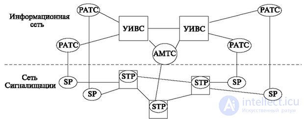
If there is a regional network (a network with nodal formation) (Fig. 9.4), the nodes act as transit signaling points and, in emergency situations, serve to organize transit routes.
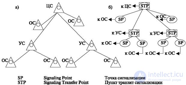
Rural signaling networks are built according to the radial system shown in Fig. 9.5.
Node and terminal stations may perform transit functions to provide alternate routes.
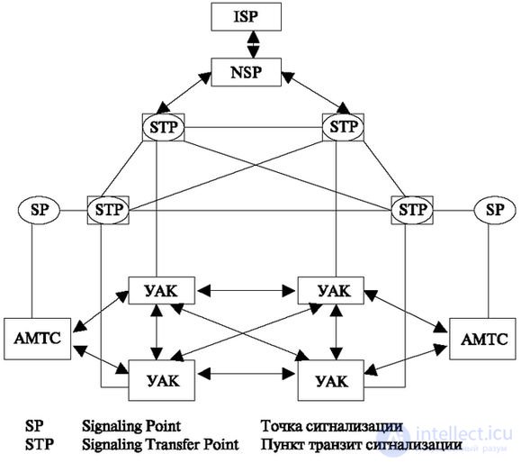
Long-distance and international signaling networks are based on the network UAK (Automatic Switching Nodes) and AMTS. The UAQ network consists of stations that are fully interconnected. Some of the telephone stations can also be connected by signaling channels (in the presence of a great deal of trouble between the zones). For greater reliability, signaling points can be connected to several transit points, as shown in Fig. 9.6.
In fig. 9.6 depicted:
In Russia, two formats of signaling point codes have been adopted, the size of which, in accordance with ITU-T recommendations, is 16 bits. They contain a network indicator (IC) consisting of 2 binary characters (ICs) and a signaling point code consisting of 14 binary characters (CPS).
When the network indicator value is “00”, the signaling point code used jointly for the international part of a long-distance and international telephone network is formed by a combination of digital symbols.
Z UUU V,
where the code of the alarm zone (Z) is 3 binary characters; Signaling Network Identification Code (UUU) - 8 binary characters; the identification code of the signaling point in the network (V) is 3 binary characters.
Thus, up to 256 signal zones (0–255) can be organized in the federal (long-distance) network, with 64 signaling points in each zone (0–63). Up to 128 (0-127) local ACS network No. 7 can be organized on the territory of each intercity zone, each of which can include up to 128 signaling points. The gateway between regional (local, zonal) networks of the ACS and the federal (long-distance) network of the zone is the AMTS zone, which is assigned a code in accordance with the national numbering plan. Specific signaling point codes are given in [46].

Comments
To leave a comment
Telecommunication Services and Devices
Terms: Telecommunication Services and Devices