Lecture
Let us first consider the structure of the digital path, which must be connected through a digital field, and the assignment of different time intervals.
The study of the information presented in this lecture can be supplemented from [8], [35].
Channels obtained by multiplexing in the PCM30 system are distributed as follows (Fig. 2.1).
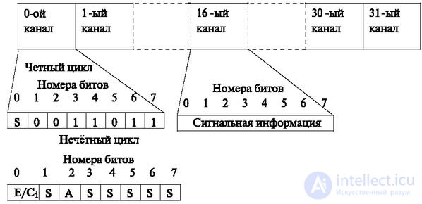
In fig. 2.1 shows the placement of information in the loop. Each consists of 32 time channels. Channels 0 and 16 carry overhead information.
In the 0th channel, every even cycle information is transmitted to synchronize the cycle. It is a 7-bit combination 0011011, placed in 1-7 bits. The first bit, indicated in figure S, is either 1 or is used to check the correctness of the transmission of information of the cycle [35]. In odd cycles, the 0th bit is provided for use by national administrations.
The variant shown in fig. 2.1, is used to transmit signaling information on the "common signaling channel" principle. In this method, the alarm for all 30 voice channels is transmitted on the 16th channel.
The second way of forming a signal channel got the name "dedicated channel". In this case, a signaling channel is assigned to each information channel.
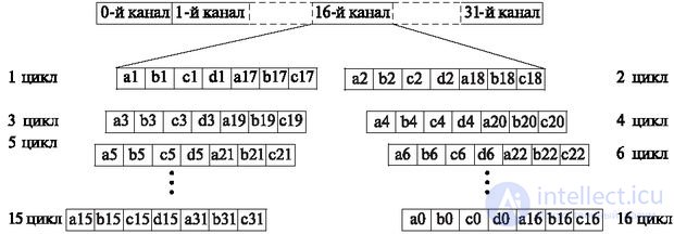
The principle of this selection is shown in Fig. 2.2. It lies in the fact that the numbering of 32-channel cycles is introduced. 16 cycles are allocated, in each of which information of the 16th channel signaling is assigned to the information channel (Fig. 2.2).
Each temporary position of the 16th channel is divided into two parts.
In the first cycle, the signal information of the 1st and 17th channels is transmitted, in the second - the 2nd and 18th, in the third - the 3rd and 19th, etc., in the fifteenth - the 15th and 31 th
In the zero and sixteenth cycles transmitted service information.
Digital switching indicates that pulsed-code or other, but digital modulation is switched. In the early stages of the development of electronic exchanges, switching signals with amplitude-pulse modulation were switched. But it did not become widespread due to the shortcomings of this type of modulation - sensitivity to distortion and interference.
In the following presentation, the type of modulation is not specified, it implies digital switching.
The following principles of digital commutation are distinguished: temporal and spatial.
Temporary switching This type of switching is based on the fact that the entire flow of information is distributed in time. In each time interval we will further briefly call it the English term slot (Slot - time interval, tact), - the information that is assigned to this position is entered.
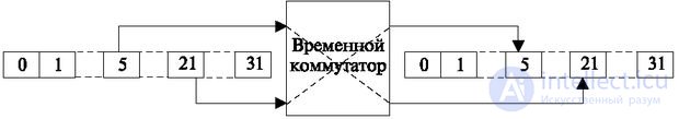
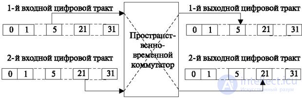
The temporary switch must transfer information from one temporary position to another given position. In fig. 2.3 shows an example when the information contained in the 5th time interval is transferred to the 21st interval.
It should be noted that since electronic switching is unidirectional (due to the fact that electronic components have only one direction), and the connection must be two-way, switching, as a rule, is carried out not only direct (5th channel with 21 m channel), but the reverse (21 channel 5). This principle is shown in Fig. 2.3.
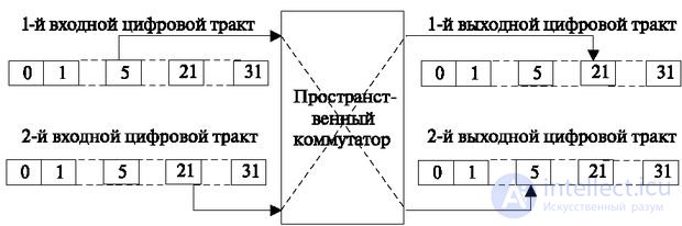
Spatial switching is that information is transferred from one time path to another without changing the time position. This is shown in the example in fig. 2.4, where information is transferred from path 1 (temporary position 5) to the second path to the same position. The same figure shows the second spatial connection.
In real telephone exchanges, both variants are used, but often combined space-time switches are used, when switching is carried out simultaneously to another path and another temporary position (Fig. 2.5).
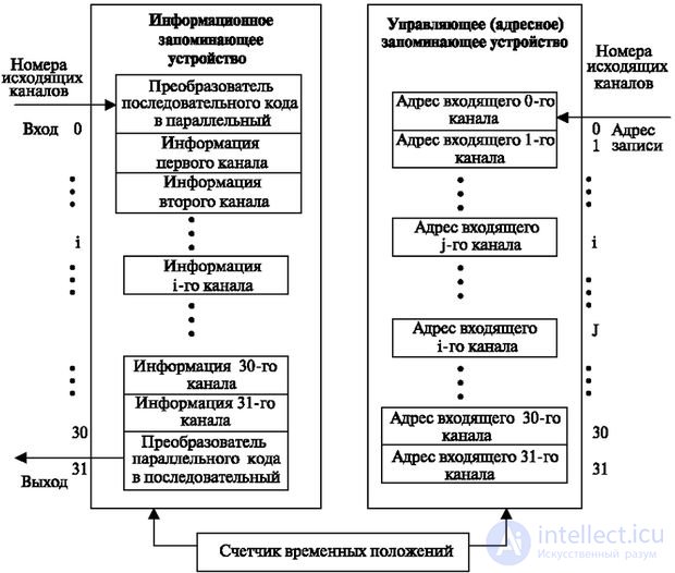
The most common method of temporal switching, i.e. transfer of information from one temporary position to another, consists in recording information into memory and reading with a delay in another temporary position (Fig. 2.6).
A serial digital stream is fed to the input of a circuit that converts information from a serial form into a parallel one.
Further, this information is recorded in the storage device. The address of the record is set by the time channel counter, which generates the numbers of the time positions in sequence.
Therefore, messages are located in the information memory as the channel number increases.
This information is read into the outgoing path in accordance with the information recorded in the address memory. This memory is also polled by the clock pulses coming from the time channel counter. Each cycle corresponds to the slot number in the outgoing stream.
The information that is recorded in this temporary position from the information memory is determined by the address coming from the address memory.
In fig. 2.6 the address of the incoming channel i is recorded in the address memory at the location of the temporary position j. Conversely, the address of the incoming channel j is recorded in the address memory at the location of the temporary position i. This means that when reading from the address memory to the temporary position j, the address i will arrive at the input of the information memory. As a result, the information received on the incoming channel (i) will be read in this temporary position (j). This is how temporary switching is implemented, the principle of which is shown in Fig. 2.3.

Comments
To leave a comment
Telecommunication Services and Devices
Terms: Telecommunication Services and Devices