Lecture
For receiving frequency and acoustic signals in digital PBX, combinations of digital samples are used - discrete [36]. To generate a signal of a certain frequency in a special storage device (frequency signal accumulator), values equal to the amplitude of the discrete are recorded. When read, they are transmitted in the direction of the subscriber terminal and are converted by the ADC into analog signals. Similarly, multi-frequency combinations are obtained for exchange with stations of existing systems.
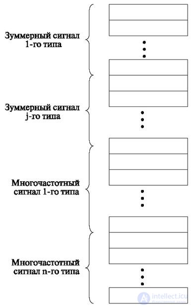
The values of digital samples are recorded in drives (Fig. 6.6). They are divided into zones. In each zone, digital samples are recorded that make up acoustic (buzzer) signals — station answer (dial tone) 425 ± 3 Hz (continuous signal), busy tone 425 ± 3 Hz (sending 0.3s – 0.4s - pause 0, 3s – 0.4s), call control is 425 ± 3 Hz (send 1s ± 0.1s; pause 4s ± 0.4s). In other zones, multi-frequency signals are recorded, providing the sending of combinations in accordance with the adopted multi-frequency signaling protocol.
The same drives can be used to transfer standard phrases and messages.
The amount of memory required to create a software generator of digital, acoustic and frequency signals is determined as follows.
The number of cells in the storage zone is determined by the frequency of the buzzer signal, for which generation this zone is intended.
This number n is equal to the number of discrete samples that come with a frequency f and = 8000 bps. If the duration of the signal period is T f (frequency f), and the period of appearance of sampling pulses is T and = 125 μs, then the number of digital samples is equal to
n = T f / T and ;
Considering that
T f = 1 / f, and T and = 1 / f and ,
will get
n = f and / f.
It is also necessary to take into account that the number of samples must be integer. Therefore, the above ratio should be multiplied by the number, which allows to reduce the denominator. Physically, such multiplication means that the number of samples (playback time) increases by that number.
As a result, we get
n = k (f and / f)
In accordance with this equation, the zone of acoustic (buzzer), multi-frequency signals is divided into subzones, each of which contains n cells, and the number of such subzones is equal to the number of periods k.
For calculations, we can formulate the following rule:
To determine the number of cells in the subzone, a sampling frequency of 8000 bps is divided by the frequency of the reproduced signal.
After reducing the fraction, the denominator will be equal to the number of periods k.
For example, to play an acoustic signal of 425 Hz (the buzzing base is "busy", "call control", "station readiness to receive a number")
n = 8000/425 = 320/17.
This means that 17 subbands are required to generate this signal and 320 samples each.
In accordance with the formula, it is easy to calculate the number n and T for the main frequencies of acoustic signals (425 Hz) and for multipart transmissions (700 Hz, 900 Hz, 1100 Hz, 1300 Hz, 1500 Hz).
The value of the digital readout is determined by the instantaneous value of the sinusoidal signal at the time of the readout using the following formula:
 ,
,
where U is the current value of the voltage signal; U m - the required signal amplitude, f - the nominal frequency required,  - The reference period is 125 µs.
x is the reference number within the period (x = 1, 2, ....., k; k is determined from the expression n = k (f H / f))
Signals are recorded in accordance with the principles of non-uniform coding (companding). In this case, the code is transmitted by a digit in the form of an 8-bit combination of the following content: "sign" + segment number "+" code inside segment ".
In accordance with the law of non-uniform coding, the quantization step q is selected, the value of which changes with increasing segment number.
For example, if the threshold limit encoder U ogre. = 3.15 V, for coding with the number of 4096 quanta, the quantum value is equal to
q = 3.15 V / 4096 = 0.768 mV.
The initial position (quantization step code 0000, segment 0000) is
q / 2 = 0.384mV.
In accordance with the law of segmental coding (Act A), the number of segments is equal to 8. In segments 000 and 001, the quantization step is the same. Next, the quantization step size in each segment is doubled (see temporary compression). The signal value itself is calculated by the formula or by the tables. Below is a table of the quantization step size for different segments (Table 6.1) [36].
| Quantization step code | Segment number | |||||||
|---|---|---|---|---|---|---|---|---|
| 000 | 001 | 010 | 011 | 100 | 101 | 110 | 111 | |
| 0000 | 0.384 | 12.67 | 25.34 | 50.69 | 101.4 | 202.7 | 405.5 | 811.0 |
| 0001 | 1.152 | 13.44 | 26.88 | 53.76 | 107.5 | 215.0 | 430.1 | 860.2 |
| 0010 | 1,920 | 14.21 | 28.41 | 56,83 | 113.7 | 227.3 | 454.7 | 909.4 |
| 0011 | 2,688 | 14.97 | 29.95 | 59.91 | 119.8 | 239.5 | 479.3 | 958.5 |
| 0100 | 3,456 | 15.74 | 31.48 | 62.98 | 126.0 | 251.8 | 503.8 | 1007.7 |
| 0101 | 4.224 | 16.51 | 33.02 | 66.05 | 132.1 | 264.1 | 528.4 | 1056.8 |
| 0110 | 4,992 | 17.28 | 34.56 | 69,12 | 138.2 | 276.5 | 553.0 | 1106.0 |
| 0111 | 5,760 | 18.05 | 36.09 | 72.19 | 144.4 | 288.8 | 577.6 | 1155.2 |
| 1000 | 6.528 | 18.81 | 37.63 | 75.27 | 150.5 | 301.1 | 602,1 | 1204.3 |
| 1001 | 7.296 | 19.58 | 39,16 | 78.34 | 156.7 | 323.3 | 626.7 | 1253.5 |
| 1010 | 8,064 | 20.35 | 40.70 | 81.41 | 162.8 | 325.6 | 651.3 | 1302.6 |
| 1011 | 8,832 | 21,12 | 42.24 | 84.48 | 169.0 | 337.9 | 675.9 | 1351.8 |
| 1100 | 9,600 | 21.89 | 43.78 | 87.56 | 175.1 | 350.2 | 700.5 | 1,400.9 |
| 1101 | 10,368 | 22.65 | 45.31 | 90.63 | 181.3 | 362.3 | 724.9 | 1449.2 |
| 1110 | 11,136 | 23.42 | 46.84, | 93.70 | 187.4 | 374.8 | 749.6 | 1499.2 |
| 1111 | 11,904 | 24.19 | 48.38 | 96.77 | 193.6 | 387.1 | 774.2 | 1548.4 |
| Step | 0.768 | 0.768 | 1,536 | 3,072 | 6.144 | 12.28 | 24.75 | 49.15 |
Interruption intervals for acoustic signals are formed by software, for example, at a frequency of 425 ± 3 Hz, the following intervals need to be formed:
Multi-frequency signals (for example, when transmitting by a two-frequency code) are generated by digitally adding the frequencies used in the corresponding modules.
For appropriate processing in the modules, acoustic, frequency signals, standard phrases and messages are divorced into the station. In this case, organized 30-channel digital path. In this path, acoustic, multi-frequency signals and standard messages are assigned to different channels of the path, as shown in Fig. 6.7.

Comments
To leave a comment
Telecommunication Services and Devices
Terms: Telecommunication Services and Devices