Lecture
When considering the principles of using time channels in digital stream with pulse-code modulation, two ways of applying the 16th channel (signaling channel) were cited [16, 17].
In the first case, control signals are transmitted for any of the channels of the path (common signaling channel) at a speed of 64 Kbps. This principle of signal transmission will be discussed further.
The second method is called the dedicated channel. In this case, each information channel is assigned a signal channel with a real transmission rate for every 4 Kbps. It was very common when communicating with electromechanical systems via digital paths. Education in the digital path of the dedicated channel has already been considered in the section on "Switching fields on the microelectronic element base" when describing Fig. 2.1. With this principle, the 16th channel is divided into two parts, 4 bits each. The principle of their use is described in detail in "Switching Fields on Microelectronic Element Base".
Tables 5.1 and 5.2 provide linear signals transmitted over two dedicated channels.
| No | Signal direction | Signal name | State of bits | Note | |||
|---|---|---|---|---|---|---|---|
| 1 VSK (a) | 2 VSK (b) | c | d | ||||
| one | ----> | OCCUPATION | one | 0 | 0 | one | Dispatched when a new call appears. |
| 2 | ----> | DIALING A NUMBER Pulse Pause Digital Interval | 0 one one | 0 0 0 | 0 0 0 | one one one | Transmission time: Pulse - 50 ms Pauses –50 ms Inter-digit spacing - 700 ms |
| 3 | ----> | DISCONNECTION | one | one | 0 | one | Transmitted in case of release of outgoing trunk (end call A, etc.) |
| four | ----> | END A | 0 | 0 | 0 | one | It can be accepted if the PBX implements a two-way hang-up system. |
| No | Signal direction | Signal name | State of bits | Note | |||
|---|---|---|---|---|---|---|---|
| 1 VSK (a) | 2 VSK (b) | c | d | ||||
| one | <---- | CONFIRMATION OF ACTIVITIES | one | one | 0 | one | Expected within 1 second after sending a busy signal |
| 2 | <---- | RESPONSE / REQUEST | one | 0 | 0 | one | Transmitted after the answer of the called subscriber. If this signal is accompanied by a frequency signal of 500 Hz over the spoken path, then it should be processed as a request for Caller ID information. |
| 3 | <---- | EMPLOYMENT | 0 | 0 | 0 | one | Transmitted by the incoming station, if the subscriber is busy, is unavailable or in case of failure of the connection establishment process |
| four | <---- | STAFF B | 0 | 0 | 0 | one | Transmitted from the incoming station, in case subscriber B hangs up. |
| five | <---- | LOCK | one | one | 0 | one | Transmitted to the outgoing station, in case of blocking of the line at the incoming station |
| 6 | <---- | CONTROL OF INITIAL CONDITION | 0 | one | 0 | one | The signal is transmitted to the incoming station after receiving the disconnect signal and releasing the line and equipment |
With the increase and complication of the functions of switching systems, it has become necessary to improve the alarm system. The most fundamental decision was the separation of information transmission chains and signal circuits [2, 26]. Such a system is implemented as follows. A signal channel is allocated to a channel group [2, 55, 63]. Information relating to the connection on any channel of the group, passes through a common channel and is accompanied by the source address.
The advantages of this method are as follows:
Disadvantages:
From the point of view of management, this disadvantage is inherent in systems with centralized management, where the ACS control program is associated with one (redundant device). In a decentralized system there may be several modules whose software controls the alarm.
Common signaling channels represent a separate network and are switched according to message switching rules. The following ways of routing signaling messages are possible (Fig. 5.1).
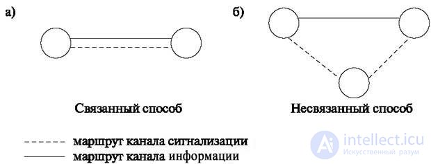
According to the first method (connected by ACS), the routing of signaling channels is carried out together with the routing of information channels. Moreover, their routes coincide, as shown in Fig. 5.1a.
The second method is a disconnected ACS: the routing of signaling information is independent of the information channels, and their routes may not coincide, as shown in Fig. 5.1b.
Often used quasi-related method, which is that the associated method is used in the normal operation of the network, and when a system fails, the system switches to redundant signaling directions that do not coincide with the information channels along the route. They are usually set in advance.
The main devices implementing ACS are shown in fig. 5.2.
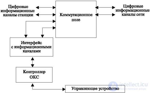
The first of them is an interface with information channels — implements an interface with a switching field. Depending on the load, the OKS inputs may occupy several inputs to the switching field. In this case, in general, they simulate a digital stream and can be switched to any channel of any path at the output. But as already mentioned, they are switched in the 16th channel of each path (recall, a typical PCM includes 30 information channels). The interface allows you to accumulate information from each signaling channel and switch it to the 16th channel of the required path.
The possibility of switching with other channels creates the possibility of eliminating emergency situations and redundancy.
The ACS controller can process signals and perform requests for lower levels of the protocol (physical and channel).
The hardware implementation of part of the protocol, as a rule, increases the speed and stability of the system.
The control device is a processor and the necessary types of memory. This is either a station control device or a module control device.
In the first case, when establishing a connection, the ACS and connection establishment software programs interact. The second requires the exchange of information with other modules.
In fig. 5.3 provides a diagram comparing the architecture of the SS7 protocol and the OSI layers [16].
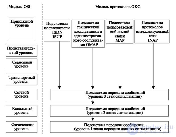
The three lower levels of the ACS protocol model are called message transfer protocols (Message Transfer Part - MTP) and are implemented primarily with the help of hardware (hardware).
Application levels are given for example, and their number and functions change with the development of switching technology. For example, the telephone signaling subsystem was recently allocated; now it is fully implemented by the ISUP subsystem, which combines the features of telephone protocols and the ISDN system. The application layer enhancement is the Transaction Capabilities Application Part (TCAP). The introduction of this subsystem allows at the application level to summarize some actions and programs, either the most frequently called, or general transitions (transactions) characteristic of several applications. Such problems are very characteristic of the services provided by Intellectual or Mobile networks.
In the subsystems of the lower level, there is a tendency to ensure the transmission through the ACS of not only data related to signal information, but also other data. In this case, it is necessary to take into account that during the transfer two groups of information units appear - connection-oriented and not connection-oriented. Within these groups, information classes appear that impose different system requirements.
This is, first of all, the requirements for time delays (whether the information is sensitive or not to this phenomenon), and in each of these classes information can be transmitted that has a constant and variable speed.
Such requirements gave rise to a signaling connection management subsystem (SCCP - Signaling Connection Control Part) at layer 3, which controls transmission over the network, depending on the type of information.
Consider the subsystems included in the model of the ACS. Let's start with a system that reveals the main signals at the user level. This will help us compare connection establishment procedures in systems without ACS and with ACS.
Then we will consider other levels that allow us to protect information, route the message and ensure the reliability of the network.
Previously listed possible subsystems of the user:
Now we need a detailed review of all types of work of these systems. Further attention will be focused on the first of them, which is thoroughly versed in this course.
It should be noted that at present the ISUP subsystem, part of the ISDN subsystem, absorbs previously developed systems.
| No | Signal name | Note |
|---|---|---|
| one | Initial Message (IAM - Initial Address Message) | Transferred to occupy the next station |
| 2 | Sequential Address Transfer (SAM - Sub Address Address) | Transmitted when working with stations that do not have ACS and require sequential transfer of numbers |
| 3 | Address complete (Subscriber found) (ACM - Address complete) | Signal about the completion of the connection. Transmitted from the last station after determining the status of the subscriber "free" |
| four | Caller Answer (ANM - Answer) | Sent when the handset is picked up. |
| five | REL - Release | Sent when an incoming station can be released |
| 6 | Disconnect (RLC - Release complete) | Transmitted at end of connection. |
| 7 | Suspend connection (SUS - Suspend) | The signal on which the connection is suspended (for example, while waiting for the second subscriber to hang up) |
| eight | Resume Connection (RES - Resume) | A signal that cancels the suspension |
| 9 | Subscriber number request (A - INR - Information request) | Request the number of subscriber A in order to provide an invoice for the services rendered or to determine the number on the subscriber’s request |
| ten | Information (INF - Information) | Number request response message |
| eleven | Blocking (BLO - Blocking) | Transmitted by outgoing or incoming station in case of need to block the line from occupation |
| 12 | Block Acknowledgment (BLA - Blocking Acknowledgment) | Sent to confirm blocking |
| 13 | Partial release (CCL - Calling Party Clear signal) | Transmitted when part of occupied appliances can be released. Message supports double-sided hang up procedure |
| 14 | Payment Message (CRG - Charge) | The message supports the start of payment procedure. |
| 15 | Starting a RNG call - (Ringing) | Transmitted after the beginning of the sending of an acoustic signal "making a call" with an incoming semi-automatic connection |
| sixteen | Subscriber Number Request (INR - Information Request) | The request is sent to issue a bill for the services provided or to identify the caller. |

Comments
To leave a comment
Telecommunication Services and Devices
Terms: Telecommunication Services and Devices