Lecture
Power installations are part of a telecommunications system and play an important role in ensuring reliable and uninterrupted system operation [22].
They provide equipment with electrical energy of direct and alternating current of the required ratings and with the required characteristics.
The power supply system contains:
The nominal constant voltage at the Russian switching stations usually corresponds to a value of –60 V. At present, in connection with the mass supply of foreign equipment to networks, it is allowed to use a nominal value of –48 V.
For a nominal value of 60 V, the allowable limits are –54 V to –66 V (± 10%).
For 48 V, they are –48 V; - 40 V; - 56V.
The voltage must be measured at the input of the current distribution panel.
Strict definitions refer these norms to static, i.e. slow deviations.
Dynamic, or short-term deviations relate more to the consumer equipment itself than to the power supply installation.
This equipment must remain operable during repeated switching on and off of the power supply or in case of derating (in the technical specification for the equipment it is necessary to stipulate the electrical safety limits for the equipment).
In modern switching systems, uninterruptible power supplies are used, which retain their parameters during sufficiently long breaks in the basic power supply from the AC network (from 4 to 8 hours). However, in the event of a catastrophic shutdown (a sudden shutdown, not accompanied by predetermined procedures and programs), all the equipment of the station must ensure a return to working condition.
At large telecommunications facilities, two power cables from independent AC sources should be introduced. The requirements for the parameters of the input voltage and frequency of alternating current are as follows:
In this case, the nonlinear distortion coefficient is allowed no more than 10%;
For example, for a station with 10,000 numbers, the current consumed by the equipment can be up to 170 A per CNN. For stations of the electromechanical system consumption will be higher. For example, for АТСК-У it is 450 А in ЧНН. It should only be noted that at electromechanical stations, current consumption depends to a large extent on the number of connections established. With a small load, energy consumption drops sharply. Stations built only on the microelement base consume current continuously.
Using the rated voltage at the stations, the following values are obtained:
± 5V - for power supply of microcircuits;
± 12V, + 24V - for power supply of the relay.
In addition, for the power supply of service devices that receive a substantial part of the service (for example, displays), it is necessary to provide guaranteed power supply with an alternating current of 220 V.
This is done by special DC-to-AC converters, which are called inverters.
The distribution network is built in one of several ways:
With the trunk method, the current distribution network is built on the basis of a single highway, which distributes power to all devices of the station (Fig. 6.8). Often this trunk is made in the form of a “ring” to increase reliability during open circuits, which may be the result of maintenance work.
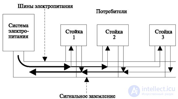
With this method, quite significant currents pass through the highway. In fig. 6.8 The passing currents are shown by lines of varying thickness. If we take into account the resistance of the conductive bus, then in the most unfavorable conditions are the devices at the end of the line. The voltage at the end of conductive wires has a lower value than at the beginning. Since the amount of current flowing depends on the load on the station, voltage drops on the wires, especially the return ones (signal grounding, as opposed to protective grounding, are sure to occur; see further section “Electrical safety”).
This affects the different sensitivity of the elements. For example, if for relays with power ratings of 60V, 24V, 12V, drops of 0.5V are not critical, then for microcircuits they are comparable to the magnitude of the input signal. At the same time, given the physical fundamentals of semiconductor technology, voltage drops on the return wire have more negative consequences than in the forward direction. In this regard, in many cases it is recommended to separate the signal ground of the electronic base from the ground of other nominal values.
The radial method of current distribution (Fig. 6.9) reduces these drawbacks.
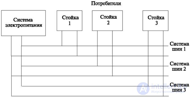
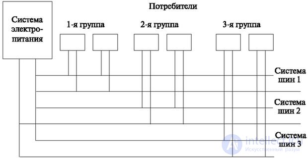
Separation of the circuits that supply current to consumers reduces the resistance of the wires that conduct the currents. Sometimes they use a mixed method - radial-main wiring (Fig. 6.10). It is more simple to install, for this consumers are divided into groups. For example, each row of equipment has a radial layout, and inside the row is a trunk.
The most common method is when a single voltage rating is diluted around the station, while others are obtained using Secondary Power Supplies (VIP), which are installed at each rack of the current consumer. This method is shown in Fig. 6.11: consumers are supplied with DC power (in the figure, for example, the most frequent case is shown —60V).
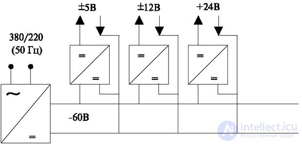
This method is somewhat expensive, but it guarantees the isolation of the power supply circuits and the installation of individual stabilizers of lesser power at each rack. At lower powers, the stabilization problem is solved much easier.
However, for a great simplification of the converters, the method of main wiring with alternating current is used (Fig. 6.12).
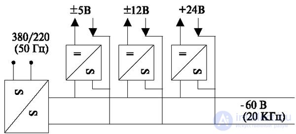
This method consists in the fact that in the central power supply device (in the figure at the leftmost side), an alternating current of 380 V (220 V) with a frequency of 50 Hz is converted to direct current, after which it is converted to an alternating but high frequency (for example, 20 kHz) and less voltage. Further, on the racks of the consumer, he again converted to permanent. Increasing the frequency allows to reduce the size of transformers, which are the main dimensional elements. Reducing the voltage allows the use of small-sized element base.
A variant of this method is wiring using broadband pulses. This method consists in transmitting from the central power supply device “wide” pulses that overlap in time. Superimposed on each other, they form, thus, an imitation of a source of direct current.
Uninterrupted power supply (UPS - Uninterruptible Power Supply) is provided by:
In the first case, parallel operation of two electric power plants is used (Fig. 6.13).

When duplicating, sometimes (at large stations), the introduction of two power cables (feeders) from an industrial current of 380 / 220V is used. Feeders are supplied either from different sources, or from different phases of a three-phase network (using single-phase rectifiers).
DC power is supplied directly from rectifiers equipped with current (voltage) stabilizers. The power of each rectifier must be designed to provide peak load.
When AC power is turned off, the station is completely stopped. This is a serious disadvantage of such a system, since most power grids do not guarantee uninterrupted power supply even if two inputs are connected. Usually, the supply contracts stipulate the right of the supplier to a break for a period of up to 2 seconds.
For all types of stations, such a break causes the disconnection of established connections.
For PBXs using electronic systems and software-controlled systems, this usually results in a complete restart of the system, which also means that the station is completely stopped.
In addition, we must take into account the great social role of telephone communication. When the electrical network fails, it remains the only means of obtaining information and communication.
Therefore, a buffer power supply system is most often used (Fig. 6.14).
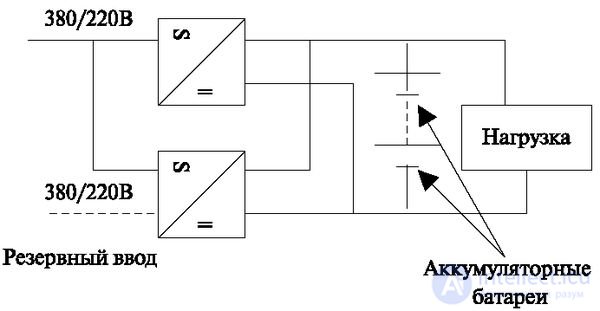
The mode of its operation lies in the fact that in parallel with the operation of the rectifiers to the load the battery works. In the presence of AC mains voltage, rectifiers provide power to the equipment and recharge the battery.
If the AC mains voltage disappears, the rectifiers stop working. The equipment is powered by a battery operating in a discharge mode.
Battery capacity is calculated on the work in the Hour of the Highest Load (CNN) for 4, and in more critical cases, and 8 hours.
The main advantages of the system are simplicity, high reliability and good dynamic characteristics of the system. Rechargeable batteries allow you to smooth out all the sudden short-term fluctuations in network parameters.
The disadvantage is large fluctuations in the output voltage due to the charge and discharge of the battery. Therefore, various solutions are used that allow, in the absence of mains voltage, gradually, as the battery discharges, to connect additional groups of batteries. During power recovery and charging, these groups are disabled.
Most modern stations use a solution based on the application of the highest possible voltage and the use of stabilizers during conversion on racks. Such a stabilizer is also installed in order to preserve the voltage in the control devices, regardless of load fluctuations (Figure 6.15).
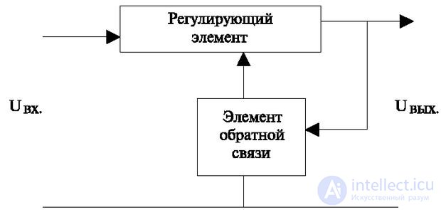
The stabilizer is usually installed at the output of a rectifier or converter. It is most convenient to use it with a decentralized power distribution method, since high-power stabilizers usually have large dimensions and cost. At its input is increased compared to the required nominal voltage. The regulating element reduces it to the required value. The output voltage parameters are controlled by the feedback element. When the output parameters change, it produces a signal to the input of the regulating element. And that either increases or decreases the voltage.
Regulatory elements are based on the principle of adjustable resistance. When impulse wiring it is possible to build it on the basis of combining the width of the pulses when converting a pulse sequence into a direct current.
The feedback element contains a reference element (for example, a Zener diode) and a circuit for comparing the output voltage with the voltage on the Zener diode. The adjustment signal is generated based on the difference of these voltages.
Of great importance in a buffer system are devices that connect batteries to the current-discharging network. They must connect and disconnect batteries without changing voltage values (without "emissions"). For large values of currents, this is a problem and is solved with the help of special switches built, for example, on Zener diodes.
To ensure reliable operation in an unreliable power supply network, the possibility of connecting diesel generators is provided. Without dwelling on this method of power supply in detail, it can be noted that its main problem is the instability of the rotational speed and, as a result, large fluctuations in the frequency of the generated power supply.
In order to ensure the protection of PBX from external and internal overvoltages, protective devices are used that are installed at all levels of power distribution (distribution network, individual consumer level). The basic requirements for these devices are dynamic characteristics. They should work faster than the equipment they protect. Therefore, the reaction time of such systems to certain voltage changes is usually specified.
The grounding system must have a protective grounding of the metal cabinets and chassis. It is combined with signal ground only at the main power supply.
Power installations are equipped with filters to separate the frequencies that create radio interference. All devices of the station must be equipped with a protective ground from external influences and radiation of the equipment itself to the outside world.
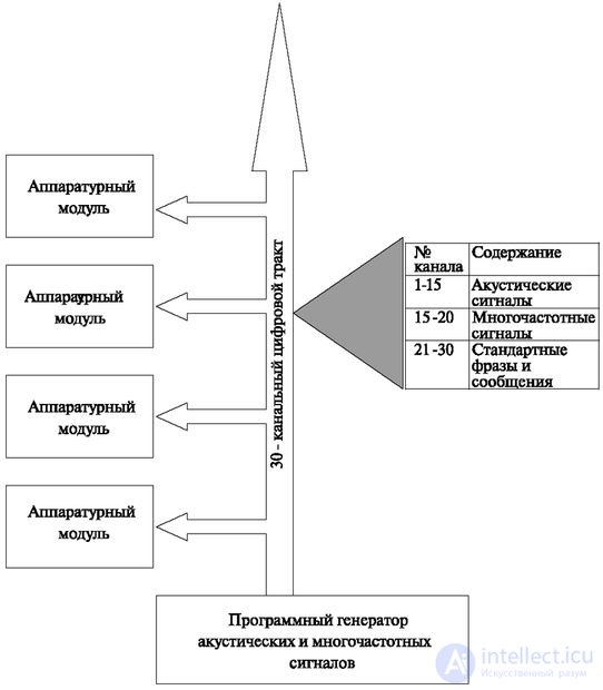
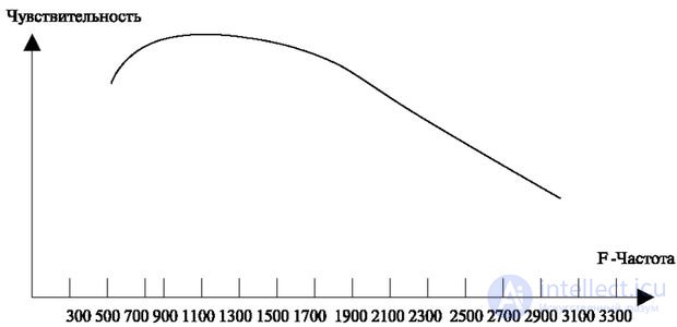
When powering devices of the vocal tract, it is necessary to take into account that human hearing organs have different sensitivity to sounds of different frequencies, and therefore the disturbances arising from the conversion of electric current must have different standards at different frequencies. To this end, it is recommended to install special filters in the circuits designed to power the spoken path, creating different attenuation depending on the frequency. The characteristic of such a filter is shown in fig. 6.16

Comments
To leave a comment
Telecommunication Services and Devices
Terms: Telecommunication Services and Devices