This section is devoted to the consideration of a rather complex issue - signaling. Suffice to say that many solid works are devoted to this problem, in particular, two-volume studies of exchange protocols [16], and a very detailed description of signaling systems [47].
Starting the analysis of this topic, two questions should be considered:
- What to transmit?
- How to transfer?
The answer to the first question will make it possible to judge "which signal should be transmitted in response to the incoming earlier, depending on the state of the system and the result of its processing?" This task is the basis for the central program. With its implementation we will get acquainted further.
The second part is responsible for the correct transmission of the already known signal and for the reliable operation of the alarm system. The algorithm (more precisely, the algorithms) of the signaling is responsible for this.
To study this question, we use the classification given in [16].
So, for transmission of signals over the communication channel are used:
- internal channel signaling;
- out-of-channel signaling;
- separate communication channels.
The first two types of signaling are used for signaling kits and devices operating in conjunction with channel equipment. Therefore, they are more relevant to the command transfer algorithm. For example, when transmitting signals over the spoken path, it is necessary to generate signals by switching on certain relays (interaction via analog lines) or by writing to certain registers (interaction via digital channels). In this case, it is enough to give an application to the command transfer module, and it will form the corresponding commands.
When using a separate signaling channel, the process of installing a command transfer request does not differ from the previous case. Currently, the 16th temporary position of the PCM tract is used as the transmission medium. The command transfer algorithm places the generated sequences into the information area of the 16th channel memory. But at the transmitting and receiving stations, special algorithms are used to convert user information into a form transmitted over the channel (signal units) and provide information protection from distortion. These tasks are performed on the so-called link level reference model [16]. The concept of a reference model plays a very large role in modern information exchange and signaling systems, but it requires quite a lengthy reasoning, therefore, those interested are again recommended to refer to [16].
We will consider the signaling algorithm in abbreviated form - on the example of a separate signaling channel and one X.25 protocol. After we introduce the possibility of using one type of signaling system, the reader will be able to independently further expand knowledge on this issue.
The block diagram of the algorithm for receiving and transmitting signal information is shown in Fig. 3.23. The input to this algorithm is an application for the transmission of control and interaction signals. The request for signal transmission indicates the memory area of the process — it contains the address of the set through which or for which the signal determined by the state of the process should be transmitted. It contains a signal that must be transmitted to the next station. The signal is encoded in accordance with the recommendations of the ITU and arrives at the output for transmission to the external environment in accordance with the protocol adopted in this direction. In addition to the signal, the algorithm generates signals about the result of the transmission of signals (the signal is transmitted, the signal is not transmitted).
For signal transmission, a buffer is organized (Fig. 3.24) for accumulating signal units (CE). Typically, the buffer is designed for the accumulation of 128 (maximum 256) signal units. They are numbered cyclically from 0 to 128 (after 128 the numbering starts from zero). These numbers are called "Direct Sequence Numbers" (PPN). Similarly, the receive buffer is organized, in which the signals are also cyclically numbered. They are respectively called "Reverse Sequence Numbers" (ARF).
Signal units are shown in Fig. 3.25. They are divided into:
- information unit;
- line state unit;
- filling unit.
The signal unit of state of the line is used to transmit the basic signals of the establishment of the connection and for the implementation of additional services.
It contains the fields shown in fig. 3.25.

Fig. 3.23. Block diagram of the algorithm for receiving and transmitting signal information
The flag field is a sequence that opens and closes a signal unit. Since the length of the signal unit is variable, the "flag" is the only sign of its end.
The check sequence allows you to detect and correct errors.
The signal information field contains information about the main signals. It is of variable length. The maximum can contain 256 bytes, but 128 are currently used.
The content of the signal information field depends on the stage of the connection and the specific signals transmitted, but in most cases it contains the obligatory part, which is shown in Fig. 3.25b. It has a volume of 40 bits (5 bytes) and consists of:
- source point (station) code - 14 bits;
- Destination (station) code - 12 bits.
Thus, the address space allows you to send a signal message to any (or any) of 4096 (2 to 12 degrees) stations.
A separate signaling channel on the physical layer uses conventional digital channels. Therefore, the address includes the number of the channel used. To do this, the channel identification code is given in the signal unit — 12 bits (2 12 = 4096).
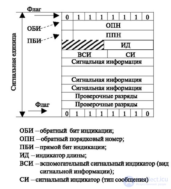
Fig. 3.24. Buffer organization for signaling units

enlarge image
Fig. 3.25. Formats of signaling units a) Basic formats for transmitting signaling information b) Example of filling in a portion of the signaling information field.
The length indicator (ID) indicates the number of bytes in the transmitted signal unit. As a maximum, it can contain 8 digits, but at present all tasks can be solved with the help of 6 digits. Therefore, 2 senior digits remain in reserve for future use.
This is followed by the bits of the auxiliary service indicator (WHI). They are divided into two groups of four bits each.
The first part defines the type of alarm:
- area and local alarms (11,000);
- long distance (1000);
- international (0000).
Each indicator triggers a different maintenance program. For example, a local connection differs sharply in the algorithm and composition of the equipment from a long-distance connection, etc.
The second part of the four bits contains information about the type of information contained in the main field:
- alarm network management (code 0000);
- maintenance and measurement of the signaling network (code 0001);
- data transmission network (codes 0110 and 0111);
- maintenance and operation of the telephone network (code 1100).
This brief and extensive description of the signal system provides only a rough idea of the content and coding of the signals.
The PBI, DPN, OBI, OBN bytes serve to ensure the reliability of the transfer, and work with them should be considered in more detail; their use is shown in fig. 3.26.
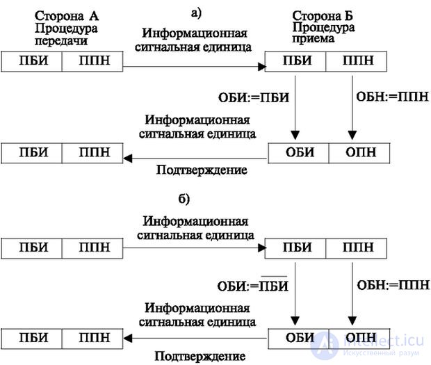
Fig. 3.26. The principle of confirmation and re-questioning signal units. a) Confirmation in case of correct reception of the signal unit, b) Re-inquiry in case of incorrect reception of the signal unit (inversion of the direct bit of the indicator)
The algorithm in fig. 3.26 consists in the fact that messages, divided into signal units and placed in the transmission buffer, are transmitted to the line. Each of the units is assigned a Direct Sequence Number - A PIT with the value of the Direct Bit of the Indication (0 or 1), this value is transmitted to the channel along with the value of the Direct Bit of the Display (PBI). The signal unit is stored in the buffer under this number until it receives confirmation of the correctness of reception of this signal unit, with the value of the Reverse Sequence Number (SPD).
A sign of correct reception is the equality of values PBI = OBI. In this case, in the transmission buffer, the signal unit for which PPN = ARF is erased.
When incorrectly received, the PBI is inverted and transmitted back. If at the transmitting end the indicators do not match (OBI is not equal to PBI), then this serves as a signal for retransmission with the same value of the PBI bit (not inverted) and the same PPN number.
The algorithm operates cyclically, i.e., information is transmitted continuously, either in normal mode or in a repeat mode or as filling units during pauses. The transmission algorithm of the signal unit is shown in fig. 3.27.
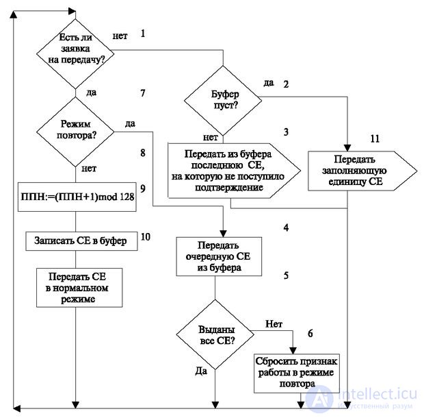
Fig. 3.27. Signal Unit Transmission Algorithm
The work begins with an analysis of the buffer applications (operator 1). Requests to this buffer are set by other algorithms or from the external environment. If there is no transfer request, then the buffer status is analyzed (operator 2); it may contain non-transmitted commands. If it is empty, then the filling unit is transferred in the format according to fig. 3.25 (operator 11). If the buffer is not empty (operator 2), this means that some signal unit (CE) is not transmitted due to distortion. Then the first unconfirmed signal unit (operator 3) is retransmitted.
If there are applications (operator 1) and there is no requirement for repetition (operator 7), then a significant unit is transferred. To this end, form the value of the PPN (operator 8). For this purpose, the next value of the Direct Sequence Number (operator 8) is formed: APN: = (PPN + 1) mod 128. Then, if there are requests and there is no repeat mode, the value unit is transferred.
Its value is set in accordance with the OBI value of the CE for which the receipt for confirmation or re-inquiry has just been received (PBI: = OBI). Before the start of the transfer, the CE is recorded in the buffer memory and transmitted in the mode specified by the data link layer protocol of the reference model (operator 10).
In the case of retransmission, statements 4, 5, 6 are executed.
The transmitted significant CEs are perceived at the receiving side, in accordance with the algorithm shown in Fig. 3.28. The algorithm is initialized when a signal arrives to receive the next CE (operator 2).

enlarge image
Fig. 3.28. Signal Information Transfer Algorithm
Further actions depend on the correspondence of the direct sequence numbers of the just-received and previous CE (PPN and PPN '). To identify this correspondence, their modulus 128 difference is calculated (operator 3).
The modulo 128 subtraction means that the difference between the numbers 0 and 127 is positive and equal to 1, that is, 0–127 = 1. This takes into account the numbering cycle in the range of 0 <PPN <127. There are four possible differences:
- The difference is less than zero, i.e., the next PPN is less than the previous one. In this case, the received CE is canceled (not accepted for further processing).
- The difference is zero, that is, the next Direct Sequence Number is equal to the previous one (operator 4). In this case, the length of the obtained CE is checked (operator 4). If its length is zero, then this is the filling unit, and an application for its processing is formed (operator 5). If not equal, then the received signal unit is canceled by returning to the idle state.
- The difference is one. This corresponds to the desired order of the significant signal units. The received signal unit is sent to the central program for processing (operator 6) and a confirmation receipt is generated (operator 7) by maintaining the compliance of OBI and PBI (OBI = PBI).
- The difference is greater than one, i.e., the next PPN exceeds the previous number by an amount that is unacceptable with the correct order of obtaining the value of the units. In this case, information is generated for the CE re-inquiry (operator 8). With such a re-request in the opposite direction, a reverse sequence number is transmitted, which is equal to the received one, but the reverse bit of the indication is assigned the value inverse to the forward bit of the indication.
It should be particularly noted that when there is a significant delay in the line, a large difference between the next transmitted and received unit is allowed, then it is negotiated, and the condition value leading to operator 8 changes.
Brief summary
- There are algorithms for the specification level and description level. Specification - displays the operation of the station from the point of view of the customer and is written using the terms of the customer. Description - represents the implementation of customer requirements.
- The algorithm is depicted as a state machine model. The following terms are used to describe its operation: INPUT, OUTPUT, STATUS, TRANSITION, SOLUTION, TASK.
- Each hardware device can be associated with a software module. It must have an external interface and be used as needed, customized. Adjustment can be carried out by quantitative indicators or a choice of modes.
- One of the most common input algorithms is scanning, i.e. input by periodic polling.
- The scanning algorithm can operate in the following modes: simple scanning, with protection, scanning by checkbox, on request.
- When the scanning algorithm works, the organization of scanning address lists plays an important role, which can lead to peak overloads or to a uniform load on the main programs.
- The principle of the scanning algorithm is that the previous state of the R1 lines and the subsequent R2 are matched and it is determined whether there are changes from the previous point in time.
- The command transfer algorithm is executed by the OUTPUT operator. He forms and transmits commands to the external environment. The process of transmitting commands is carried out in several stages: the first stage is the formation of commands, the second is the issuance of commands, the third is the control of the command execution.
- The principle of operation of the command transfer algorithm: it matches each pair of states (previous and subsequent) a sequence of commands.
- The algorithm for receiving the number of the called subscriber is designed to fix the number of the called subscriber. It should be able to receive a number from a disk and multi-frequency dialer.
- Number reception algorithm provides: reception and accumulation of pulses from disk and multi-frequency dialers; interdigit definition; reception and accumulation of either digits from the dialer, or accumulated number of pulses from a disk dialer; definition of the end of the dialing; the formation of applications for algorithms for further processing of the call; referring to the "timer" algorithm for counting the interdigital interval and receiving signals from this algorithm.
- The decoding, number analysis and direction selection algorithm recalculates one number or a set of numbers into others.
- A simple algorithm for recalculation is a single-stage decryption using a table, when each source number to be recalculated is assigned one row of the table to which the corresponding number is written in another numbering system.
- To reduce the amount of recalculation, you can apply a consistent principle of analysis. With this method, each individual digit is sequentially analyzed.
- The intermediate paths search algorithm is intended for finding a free and available call line if there is a multi-stage switching system at the station.
- The principle of the algorithm in the conditional search consists in the sequential determination of the overall vacancy of the sections of the tracks according to the availability graph, with which all available paths between two points are depicted.
- The algorithm for receiving and transmitting signaling information transmits and receives signals for interaction and control, and processes them in accordance with the data link layer protocols.

Comments
To leave a comment
Telecommunication Services and Devices
Terms: Telecommunication Services and Devices