Lecture
As already noted in the previous sections, it is most expedient to build switching fields for high-capacity stations using multi-stage circuits. Let's talk about the options for grouping such stations. The most common use of cascades based on space-time switching. However, in some popular systems, only spatial switches are used as intermediate stages for temporal flows. Let us consider one of such examples (Fig. 2.13) - the switching field of a station of small (medium capacity) with compression, made according to the principle "time - space-time" (В-П-В).
It has at the entrance 64 temporary paths. The size of the channels of the tract may be different, for example, 32 channels. Then the number of channels at the input is 2048 (or 1024 duplex connections).
If you enter another stage of spatial switching, the switched capacity can be increased several times.
In the case of using only space-time switching, of great interest is the so-called one-sided grouping (with the “reflection” level) (Fig. 2.14).
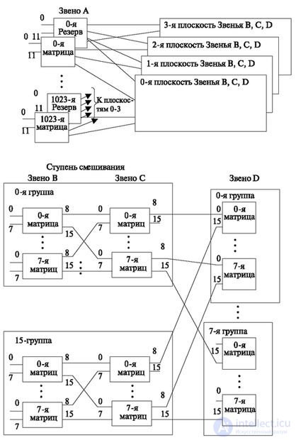
This type of grouping is characterized by the fact that all sources of load are concentrated in the same matrices. Compared with the groups of groups already studied, there is no party to which only sources of one type are included (for example, subscriber sets, payphones and other terminals), and on the other hand only channel objects (incoming and outgoing sets). In previous systems, this necessitated the creation of concentration steps. In this case, the connection of sources with sharply differing loads requires their initial distribution over different matrices of the first stage in such a way that the average input load corresponds to a given quality of service and is determined by calculations based on the teletraffic theory. However, as shown in fig. 2.15a, if necessary, you can put the compression stage in the form of a matrix 12x4 (link A). The compression stage also performs reliability functions in many station configurations. In this case, it provides access from the input paths to the four planes of the switching field.
This implements a fourfold switching field reserve (one of the blocks that significantly affect the reliability of the station). However, in most cases double reserve (duplication) is used. In this case, either some of the outputs of the link A remain unused, or two lines lead to each plane from the concentration level, which reduces the maximum number of inputs. But, as can be seen from the figure, the number of inputs already reaches a high value. Since link A performs the functions of ensuring reliability, it is installed even in cases where the load does not require compression. In this case, do not use all the inputs of this link.
According to fig. 2.14b, the plane has 16 groups (links B and C, groups from 0th to 15th). Each group is designed to include 64 paths. This amounts to 1024 tracts. When you turn on the concentration level (taking into account the reserve level of concentration), the total number of inputs will be 1024 . 12/2 = 6192 path, each path has 32 channels, which is quite enough to create high-capacity stations (for example, 65000 subscribers and 32000 channels).
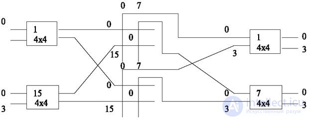
The first matrix of each group (link B) is available 8 matrices of the link C. The last link D is called the link of "reflection". The connection at this stage is “reflected”, as it were, and the establishment of a connection to another input goes in the opposite direction to the first stage. It should be noted that if a connection is established between the ports in this grouping scheme, then a free search is carried out to this stage, and a forced search after it.
Despite the potentially large number of included lines, this grouping allows you to gradually increase the station from the minimum capacity to the maximum, without changing the search and control algorithm. This property is ensured by the property of commutation matrices, as well as field control features. As already noted (Fig. 2.12), the connection can be made within the same matrix of any link, therefore any link can be reflective.
In fig. 2.15 illustrates the principle of increasing the station on the above matrices.
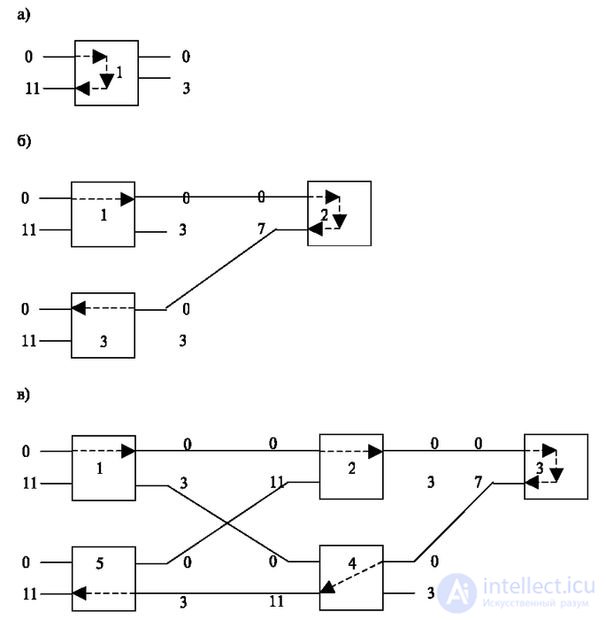
In fig. 2.15 shows the build-up of links with increasing station capacity. At the same time, the number of free line search commands should increase. This number is odd and is equal to 1, 3, 5, and the full scheme requires 7 commands (in Fig. 2.15 it is not shown, as it repeats Fig. 2.14).
These commands are issued by an external source that is included in the inputs of stage A. It determines the number of commands by comparing the outgoing and incoming addresses. Each input to the switching field can be numbered. The room includes:
Total - 14 bits.
The number of required commands is determined by the controlling device of the module that controls the connection. Suppose you need to establish a connection between the outgoing point included in the port with the number ABCD and A 1 B 1 C 1 D 1 . The bitwise comparison of these numbers allows you to determine the required number of commands to establish a connection.
If a  ,
,  , C = C 1 and D = D 1 , then the connection is established only within the limits of link A and 1 command must be sent.
If a  ,
,  , C = C 1 and D = D 1 , then the connection is established within the A and B links and 3 commands are transmitted.
If a , ,  and D = D 1 , then the connection is established within the A, B and C links and 5 commands must be transmitted.
If a , , ,  then the connection is established within the A, B, C and D links, with 7 commands being passed.
This principle of control allows not to change the algorithm of operation of external modules and search for intermediate paths depending on the composition and capacity of the station.
So, three principles of construction of switching fields are considered.
Familiarity with them allows you to view and create other types. Based on the considered field types, switching systems are built.

Comments
To leave a comment
Telecommunication Services and Devices
Terms: Telecommunication Services and Devices