2.6 Set of analog subscriber line electronic station

Lecture


Currently, subscriber sets in electronic PBXs are largely unified and run on microelectronic elements (except relay and transformer circuits). The full list of functions for a set made on the basis of electronic circuits is usually denoted by the abbreviation BORSCHT:

  • B - (Battery feed) - power supply;
  • O - (Overload Protection) - protection against hazardous voltages;
  • R - (Ringing) - sending ringing signals;
  • S - (Supervision) - monitoring the state of the loop;
  • C - (Coding) - coding;
  • H - (Hybrid) - implementation of the differential system;
  • T - Testing - testing subscriber lines.

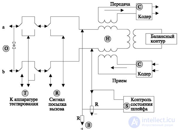
The scheme of such a set is shown in Fig. 2.19. The terminal’s power supply (for example, microphone and logical part) is supplied from a stationary battery of 60 V with a grounded positive pole (function B). (function S).

The protection functions against hazardous voltages (O) are performed at two points of the subscriber loop: at the station's cross-connect and in the subscriber set.

The first protects against short-term overvoltages (for example, from lightning voltage falling on the line). Therefore, the protection devices in the cross-country got the name of "thunderbolts". They work "for breakdown", i.e., under the influence of overvoltage, they short circuit the entrance of the station and, when the pulse disappears, they restore the normal circuit again.

In the subscriber set, the protection works on the principle of a fuse, i.e., as the current or voltage increases, the protection insert “burns out” and terminates the subscriber loop. In electronic stations, one of the main problems of protection is that the speed of protective devices must be greater than the speed of the main circuits. In other words, protection should work before the work of the main circuits is disturbed. In this regard, high requirements are placed on the performance characteristics of protective circuits.

The reaction time for impulses with very stringent requirements for the duration of the leading edges and the blocking time of the main circuits is stipulated.

The R function provides a ring-back signal. The magnitude of the voltage of this signal is 90V. The parameters of this signal and possible options for its implementation were considered in the first section. The most common current signal of alternating current frequency of 25 Hz. To prevent the relay contacts from burning out, its switching off and on is synchronized with the moments when the signal is zero.

Encoding and decoding (Function C). It takes place with the help of a coder and a decoder, made in the form of one device (codec).

The implementation of the functions of the differential system (function H). The function is implemented using transformer circuits. The principle of its work was shown in the book [7] (see. Fig. 6.1). The balance circuit, built on resistors and capacitors, can be programmatically adjustable and tune to a specific line.

Test subscriber lines (function T). The control parameters of the subscriber line by using the contacts of two relays. They allow you to connect test equipment to the subscriber line or in the direction of the station.

Test equipment (total per group or per station) allows monitoring the parameters of the subscriber line or conducting testing of the station from the subscriber side, connecting the subscriber, simulating the load, etc.

The subscriber bundle is one of the most popular devices of the station; therefore, much work is being done on its micro-miniaturization. Chipsets that implement its functions are abbreviated as SLIC (Subscriber Line Interface Circuit).

  2.6 Set of analog subscriber line electronic station

Fig. 2.19. Subscriber analog kit of electronic PBX

Brief summary

  • The following principles of electronic (digital) switching are distinguished: temporal and spatial. Digital switching indicates that pulsed-code or other, but digital modulation is switched.
  • Temporary switching implies that the entire flow of information is distributed in time - information is assigned to the temporary position.
  • In each time interval, called by its English term slot (slot - time interval, tact), information is assigned that is assigned to this position.
  • Spatial switching is that information is transferred from one time path to another without changing the time position.
  • The “common signaling channel” principle is used to transmit signaling information. In this case, the alarm for all 30 voice channels is transmitted on the 16th channel.
  • The second way of forming a signal channel got the name "dedicated channel". In this case, a signaling channel is assigned to each information channel.
  • The most common method of temporal switching is as follows: information is recorded in a storage device, the address of the record is set by the counter of time channels, which generates in sequence the numbers of temporary positions. This information is read into the outgoing path in accordance with the information recorded in the address memory.
  • The principle of constructing a space-time switch using a storage device is almost the same as for a temporary switch. Information memory is set for each digital path. Address memory is installed in a volume equal to the total number of channels of all paths, and controls all paths on the basis of time switching.
  • Complex circuits are used to build space-time switches. They are divided into the outgoing and incoming parts and have a connecting line consisting of many tires.
  • Control formats are used to control complex switching elements.
  • As already noted in the previous sections, it is most expedient to build switching fields for high-capacity stations using multi-stage circuits. The most common use of cascades based on space-time switching.
  • One-sided grouping (with the degree of "reflection") is characterized by the fact that all sources of stress are concentrated in the same matrices.
  • The last link is called the "reflection" link. The connection at this stage is “reflected”, as it were, and the establishment of a connection to another input goes in the opposite direction to the first stage. It should be noted that if connections are established between the ports in this grouping scheme, then a free search is carried out to this stage, and a forced search after it.
  • Despite the potentially large number of included lines, this grouping allows you to gradually increase the station from the minimum capacity to the maximum, without changing the search and control algorithm.

Comments


To leave a comment
If you have any suggestion, idea, thanks or comment, feel free to write. We really value feedback and are glad to hear your opinion.
To reply

Telecommunication Services and Devices

Terms: Telecommunication Services and Devices