Lecture
To perform this function, a part of the signal information field (the SIF field) is used, which is called the routing label (Routing Label) (Fig. 5.8). We considered this part for some signaling units (see Tables 5.4-5.13).
Using the code of the incoming message point (DPC - Destination Point Code), the signal processing function can determine to which end point of the network the message has been sent (for example, Moscow, St. Petersburg, etc.). If there are several hard paths for transmitting signaling information, then a signaling link selection field (SLS) is used to select the signaling link at each hop.
There are two main uses for the SLS field, namely:
An example of such a case is a beam of channels directly connecting the outgoing and incoming stations with associated signaling channels of the ACS (Fig. 5.12).

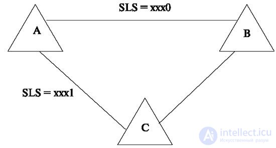
In the case of the use of workarounds, the information reaches the end point and the signaling is split along signaling channels that belong to different directions (Figure 5.13).
Load sharing across transit stations can be used in various ways. For example, for reserving, when in the event of a signaling malfunction from station A to B, the information may pass in a different way (depending on the SLS and the end point field), or in load sharing mode, when part of the signal information is subject to certain conditions (by load level , depending on the time of day or type of payload) can choose a route in another direction.

In fig. Figure 5.14 shows the structure using bypass paths in the two signaling links. The message routes correspond to the following SLS:
  ACEB SLS = xx00
 ACFB SLS = xx01
 A- DEB SLS = xx10
 ADFB SLS = xx11
The function of processing level 3 messages. The operation algorithm for the function of processing level 3 messages is as follows.
When receiving, by the message processing function of a signal unit from Layer 2, a Destination Destination Code (DPC) is analyzed to determine if this signal unit is intended for a receiving signaling point. If it is intended for this item, then it is delivered to the subsystem of the user.
To transfer information to the user subsystem (ISUP), the Service Information Octet field SIO is used. It consists of a pointer to the SF subsystem (Sub service Filed) and a service indicator SI (Service Indicator). The SI field is used to indicate the type of networks that use this signaling. For example, it serves to separate messages destined for intercity and international networks. The field contains four bits, of which 2 are currently used, and the other 2 are reserved. An example of the distribution of the SF codes is shown in Table 5.14, and of the SI codes in Table 5.15.
| DC bit value | Name of information |
|---|---|
| 00 | International messages |
| 01 | Intercity national communications |
| ten | Reserve for long distance use |
| eleven | Reserved for national use. |
| DCBA bit value | Name of information |
|---|---|
| 0000 | Alarm Management Network Message |
| 0001 | Messages testing and maintenance of network alarms |
| 0010 | Reserve for national use |
| 0011 | SCCP (Signaling Connection Control Part) |
| 0100 | ISUP subsystem |
If the message was intended for another signaling point (this point is transit), then after analyzing the destination code, a route is selected in accordance with this code and the value of the SLS signaling link selection field.
Consider another set of functions performed at the network level of the signaling transfer subsystem (MTP), the signaling network control functions (Fig. 5.15).

These functions are divided into three groups:
The signal traffic control function (Fig. 5.15a) provides the procedures necessary to maintain the signaling traffic in case of violations in the signaling network. This feature includes the following procedures:
The transition to the backup link transfers the signaling traffic from the inaccessible signaling link to the alternative link. Example: transition in case of failure of an alarm link. Such a transition should be performed without losing the message, duplicating or disrupting the sequence of message transmission. This is achieved by accumulating information in the retransmission buffer and replay algorithms. If there are no alternative paths, the destination is considered unavailable. The subsystem of the user is informed about this.
The procedure for returning to the original signaling link is initiated when the reasons that caused the transfer to the reserve are eliminated. This restores the old signaling message routing system. The procedures of this function provide the elimination of distortions and changes in the sequence of transmission of signal units.
The procedure to prohibit signaling link control is used to facilitate maintenance and testing. The procedure does not cause a state change at level 3, leaving the link available only for sending maintenance and testing messages.
If there are situations in the network when it is necessary to use prohibited signaling links, the inhibit procedure can be ignored, and these links are included in the operation.
The control function of the signaling links (Fig.5.15b) ensures the creation of signaling links and maintaining their availability. Basic procedures:
Activation of the signaling link is a process leading the signaling link to the state of readiness to serve traffic. It involves establishing initial phasing of the signaling link and testing to ensure correct operation. Deactivation takes the link out of service.
The restoration of the signaling link coincides with the activation procedure, but is used to reintroduce the signaling link to work after its failure.
The signaling route control function (Fig. 5.15c) is used to distribute network state information to block or unblock signaling routes.
Basic procedures:
The procedure for prohibiting the use of a route is initiated by a transit signaling point in order to notify one or more signaling points of a transit ban to a specific destination.
The ban can relate to certain types of traffic. For example, the prohibition of local connections, the prohibition of long-distance connections.
The procedure for enabling the use of the route removes the status of the ban.
The beam test procedure initiates a routing check, the beam test message contains destination information received by the transit point. Upon receipt of this message, the transit signaling point compares the state of the destination indicated in the message with the actual state. If they are different, the result is returned to the destination.

Comments
To leave a comment
Telecommunication Services and Devices
Terms: Telecommunication Services and Devices