Lecture
In this section, the stations intended for operation in telephone networks will be mainly considered. These issues form the basis of telecommunications and have been studied for many decades. There are a number of textbooks ([1], [28], [35], [17]) that are basic when studying this material, despite the fact that currently many of the issues outlined in this literature need to be adapted to modern technology . The development of telecommunications technology has led to integration, covering the network of information first (for example, voice and data transmission networks), and then the corresponding services. As a result of the integration processes that are gaining momentum, it is impossible to limit ourselves to the consideration of speech transmission tasks only; therefore, other principles of switching and information processing will be considered. The basic principles of the construction of switching stations do not depend on which base (mechanical elements or computer equipment) the stations are performed on. As we will see later, decisions on the construction of stations are dictated primarily by economic and technical requirements, thus creating the possibility of implementing new services for subscribers.
Today we can observe a wide variety of both telephone exchanges and switching information processing nodes. However, they all contain certain groups of devices (Fig. 1.1).
Consider the tasks performed by each part of the station.
The switching field solves the problem of connecting two or more sources together. At the first stages of the introduction of telephone technology, this role was played by electromechanical devices based on electromagnetic elements. These basic elements defined the names for the first switching systems:
With the advent of the microelement base and the development of electronic computing technology, a whole range of digital transmission systems and corresponding digital switching systems were developed. Currently, more and more switching tasks are performed in conjunction with management tasks. Improving the speed allows you to combine these tasks and thus leads to further progress of information switching technology.
The control unit solves the logical tasks necessary to establish a connection, and also performs work related to basic and additional services. The first PBX systems used control devices based on electromagnetic relays, which are essentially slow computers. The number of tasks solved by them was limited due to their rather poor logical capabilities and a long execution time. In the future, as microcomputers developed, universal computer equipment began to be used for the management of PBX systems, and now all parts of the telephone station are implemented on it. Therefore, along with the existing methods of building and managing networks that are typical of traditional telephony, methods inherent in computer networks (for example, packet transmission, address switching, etc.) have become more widespread. In the transition to control using computers, another significant component appeared - this software, which takes over all the tasks of managing the station (except for the physical and some functions of the data link level).
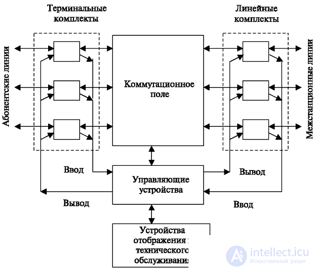
The general structural diagram of a modern programmed station (Fig. 1.1) also includes:
Let us consider in more detail the structure of building stations on the example of telephone stations. Features of the construction of other objects switching information will be analyzed separately.
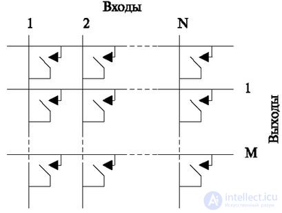
For the simplest type of switching field - the fully accessible switching field - it is characteristic that each source included in its input can be connected to a source included in the output.
This type of switching field was used in stations of very small capacity (up to 50 numbers and less). But recently the progress of the element base expands the possibilities of its application.
Preliminarily, we can say that information network switches now work on the same principle, but gradually modern switches, even on the basis of software routers, are switching to multi-tier schemes.
In fig. 1.2 shows the construction of the conventional scheme of the switch. At each intersection of the horizontal and vertical of the switch, a contact is conventionally shown, for simplicity, a mechanical one.
The physical principle of the implementation of such a contact can be anything, including program-addressed.
Such fully accessible principles for the construction of the switching field were not widely used because of their inefficiency for high-capacity stations. Only recently, due to the reduction in size and cheapening of circuits implementing switches, has it become possible to apply this principle to building stations of sufficiently large capacity (more than 2,000 inputs / outputs). But modern stations often have large capacities, up to 300,000 inputs and 100,000 outputs. In this case, such a matrix simply cannot be performed, given its real price and size.
Recently, in many important switching applications, software methods are used that are executed on computers.
These switching methods are equivalent to a full-access scheme. But with large capacities, one computer cannot provide service for incoming call flows, neither in speed, nor in memory volumes. Therefore, at the software level, a search for solutions equivalent to multilink switching is required.
With a large number of users, switching circuits containing many links are more efficient. In fig. 1.3 shows a two-tier switching circuit. To determine the areas of application, we compare the previous and subsequent schemes by the number of switching points required.
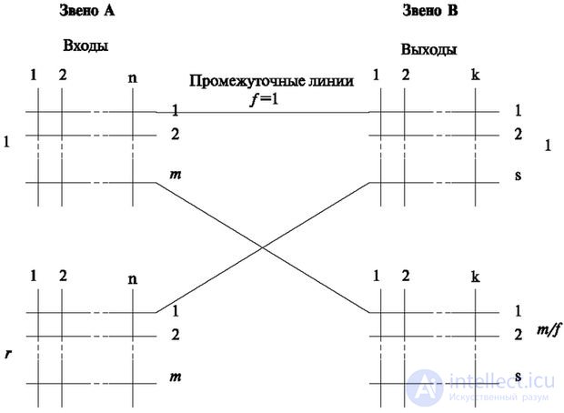
In fig. 1.3 the following notation is used:
Connectivity is the number of intermediate lines that connect one specific matrix of the link A to one specific matrix of the link B.
Let it be necessary to switch N inputs with M outputs. Then the following conditions will be met: for a fully accessible switching circuit, the number of switching points is NM;
For a non-complete switching scheme, the number of switching points is r (nm) + m / f (ks).
However, r (the number of switches of the link A) depends on the required total number of inputs N and is
r = n / n.
At the same time, m / f (the number of switches of the link B) depends on the required total number of outputs M:
m / f = M / k.
Then the number of switching points of the incomplete switching circuit will be Nm + Ms.
This determines the condition: for a multi-link switching circuit to be more efficient than a single link, the number of switching points in it must be less than in the fully accessible one:
  NM> Nm + Ms
 1> m / m + s / n.
The last condition can correspond to many combinations of parameters of switching circuits, but for all of them it is true that the following relations are observed
m / M <1 and s / N <1 (where N, M, m, s 0).
These requirements mean that the number of outputs of the matrix of the link A should not exceed the total number of outputs of the entire switching circuit M, and the number of inputs of the link B should not exceed the total number of inputs to the switching circuit N.
This condition is satisfied for all real-world tasks. The number of matrix outputs that are presently available for small stations (from 100-500 inputs and the same output range) varies from 4 to 8, and for large capacities (4000-300000 inputs and outputs) there are matrices of 512 outputs.
From the above data it follows that in modern telephone exchanges single-link switching circuits are many times less economical than multi-link ones.
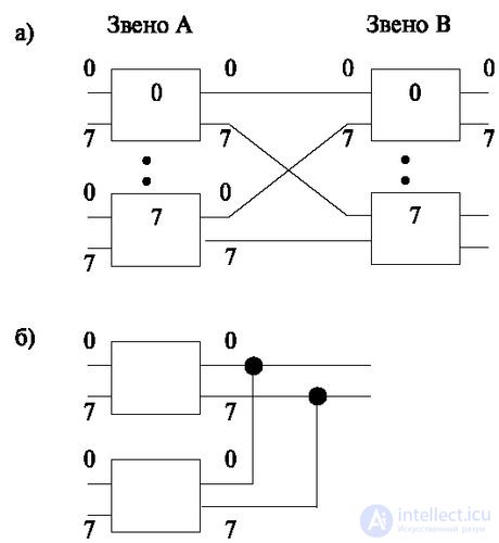
However, a small number of inputs to the switching matrix does not allow the construction of a two-link switching scheme with a sufficiently large number of outputs. For these cases, multilink schemes are used (see, for example, Fig. 1.4).
In fig. 1.4a shows a block containing 8 8x8 switching matrices. It has a total number of inputs N = 64 and outputs M = 64. To increase the number of inputs and outputs, a circuit of 8 blocks is built (Fig. 1.4b), which allows increasing the number of inputs and outputs to N = M = 512.
Shown in fig. 1.4 The switching circuit has an equal number of inputs and outputs. However, various types of units are used to build telephone systems. They differ not only in the parameters of switches and the number of cascades, but also in their purpose.

For example, it is known that the level of subscriber lines is rather low (with the exception of payphones, lines with Internet terminals). On average, they are used per hour by 10-15%. For inter-office lines, the cost of which is very high, it is necessary to increase the intensity of use and thereby reduce the requirements for the number of lines allocated to a given group of subscribers. Therefore, special schemes with concentration are used to turn on subscriber lines (Fig. 1.5).
To create a concentration, matrices are used that have a number of inputs greater than the number of outputs. This can be achieved constructively or by paralleling the outputs (Fig. 1.5). In digital switching systems are widely used options when the concentration by paralleling is done on the subscriber (terminal) sets, which brings additional convenience. When considering the construction of terminal kits will be considered such options.

Comments
To leave a comment
Telecommunication Services and Devices
Terms: Telecommunication Services and Devices