Lecture
The generator can be built on any amplifying element covered by positive feedback. A generalized diagram of the generator of undamped oscillations is shown in Fig. one.
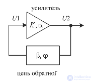
Figure 1. Generalized generator circuit
For self-excitation of oscillations in such a scheme, two conditions must be met:
The amplitude balance is performed if the product of the gain of the amplifier K and the transmission coefficient of the feedback circuit  will be more than one:

Phase balance is performed if the sum of the phase shift of the amplifier  and phase shift feedback circuit
  will be zero or a multiple of 360 °:
where n is an integer
As an amplifying element, you can use any active element that has a gain. In the case of designing a local oscillator, it is most convenient to use a transistor. It is known that inductive and capacitive three-point circuits are used to build an oscillator with transistors. These circuits are called oscillatory circuits. Currently, the inductive three-point circuit is practically not used. This is due to the high cost of inductances.
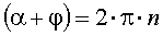
Capacitive three points also have three options for the inclusion of an oscillating circuit. These options in the English-language literature have their own names. Their schemes are shown in Figures 2 ... 4.
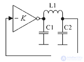
Figure 2. Pier chart
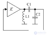
Figure 3. Scheme of the Kolpitz
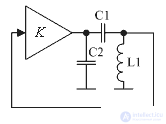
Figure 4. Klapp scheme
Any of these generator circuits can be used to implement the local oscillator. Figure 5 shows an example of a Kolpitz scheme made on a bipolar transistor.
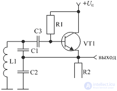
Figure 5. Klapp circuit made on a bipolar transistor
In this circuit, an amplifying element (transistor VT1) is included in the circuit of L1 C1 C2, the resonant frequency of which sets the frequency of generation of the circuit. The depth of feedback is determined by the ratio of capacitances C2 and C3 of the circuit and the gain of the transistor at a given self-excitation frequency.
The decoupling capacitor C3 does not allow the inductance L1 to short the base of the transistor VT1 onto the dc circuit case, therefore the dc current stabilization circuit can be considered independently.
In this scheme the scheme of collector stabilization is applied. In the generator circuit, in most cases, for stabilization of the mode, this type of stabilization of the current of the transistor is enough. This leads to a decrease in the voltage U be, since according to Kirgoff's law, the voltage at the base can be described as follows:

where you can express the voltage U be:

Reducing the voltage U be leads to a decrease in the base current of the transistor and ultimately to the stabilization of the rest current of the transistor VT1.
As another example of the concept of the local oscillator, Figure 6 shows a Kolpitz scheme made with a bipolar transistor.
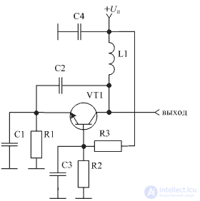
Figure 6. The scheme of the Kolpitz made on a bipolar transistor
In the heterodyne circuit, shown in Figure 6, a DC emitter stabilization circuit is applied. In it, the base voltage divider is assembled on resistors R2 and R3, and the emitter resistor is R1. The rest of the circuit of the transistor on a direct current does not differ from the circuit of the transistor, shown in Figure 5.
In the heterodyne circuit shown in Figure 6, the transistor is connected according to the common base circuit. This allows you to apply this scheme of the local oscillator at very high frequencies. As in the switching circuit of a transistor with a common collector, it does not invert the input signal, therefore, for self-excitation of oscillations, it is enough to feed a part of the oscillation energy from the output circuit. The frequency-defining parallel circuit in this heterodyne circuit consists of elements L1, C1, C2. The depth of feedback is determined by the ratio of capacitors C1 and C2. High-capacity decoupling capacitor C4 provides grounding of the upper end of the inductance L1. Capacitor C3 provides the grounding of the base transistor VT1 AC.
For LO, it is very important to ensure the stability of the generated frequency. In this case, the impact of powerful interference acting on the output of the local oscillator, can lead to the capture of its frequency or to spurious frequency modulation interference. That is why it is very important to ensure the minimum effect of the load on the frequency of oscillation generated by the local oscillator of the receiver. Especially this requirement concerns the first local oscillator.
The isolation of the output and input circuits is usually performed with an amplifier on a transistor or integrated circuit. At the same time, the energy from the local oscillator can be taken less, which will reduce the insertion loss in the frequency-setting loop and, ultimately, increase the frequency stability of the local oscillator.
As a decoupling device, any amplifier can be suitable, however, a transistor amplifier with a common collector (emitter follower) is most often used. A similar scheme of the local oscillator with decoupling from the mixer using an emitter follower with galvanic coupling between the amplifier stages is shown in Figure 7.
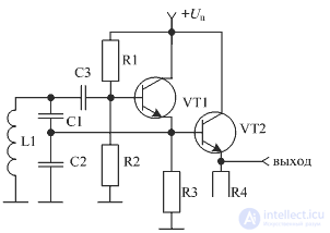
Figure 7. Load-Loop Loop with Emitter Repeater
At present, integrated circuits are used as a buffer amplifier, which allow obtaining the normalized gain and decoupling of the input of the chip from its output in the entire operating frequency range. As an example, you can call the MAX2470 MAX2470 buffer chip from MAXIM. Due to its small size, this microcircuit occupies an area smaller than the circuit assembled on separate elements.
There are chips in which to realize the local oscillator it is enough to connect only external inductance. As a similar chip can be called a chip MAX2605. Nevertheless, the construction of the local oscillator and a number of companies, such as Mini-Circuits or Sirenza microdevices, produce ready-made modules of local oscillators, designed to work in a specific frequency range, for obtaining quality characteristics.
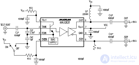
Figure 8. A local oscillator circuit implemented on the MAX2620 specialized chip
The stability of the local oscillator frequency has a great influence on the stability and noise parameters of the power source, therefore, when implementing the local oscillators, much attention is paid to the local oscillator power circuits.
Initially, to reduce the level of voltage ripples present on the power source of the receiving device, filter circuits were placed along the heterodyne supply circuits. These chains reduce the effect of the remaining receiver units on the frequency of the signal produced by the local oscillator.
As the integrated circuits improved, low-noise voltage stabilizers began to be used as active filters. An example of such a stabilizer is the ADP3330 chip from ANALOG DEVISES. A local oscillator circuit using the ADP3330 low noise stabilizer as a power filter is shown in Figure 9.
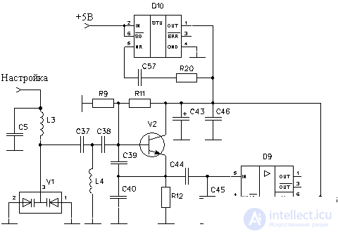
Figure 9. A local oscillator circuit with a low-noise voltage stabilizer
In this scheme, as a cascade, reducing the influence of the mixer on the output frequency of the local oscillator, the MAX2470 buffering chip is used. Chain R20, C57 is designed to reduce noise at the output of the chip low-voltage voltage regulator ADP3330, used as a filter for the power of the local oscillator.
In addition to the instability of the supply voltages and the load, the value of the generated frequency is affected by aging and temperature dependence of the frequency-generating elements (inductances and capacitors that make up the circuit). In order to ensure the stability of the generated frequency, inductances and capacitances are used with a low temperature dependence. In some cases, several capacitors with the opposite dependence on temperature are used.

Comments
To leave a comment
Devices for the reception and processing of radio signals, Transmission, reception and processing of signals
Terms: Devices for the reception and processing of radio signals, Transmission, reception and processing of signals