Lecture
In some cases, in a superheterodyne receiver, it is very difficult to satisfy the requirements for suppressing the frequency of the mirror channel and the adjacent channel simultaneously. In this case, additional suppression of the mirror channel in the mixer can be a way out. In order to understand how the mixer works with the suppression of the mirror channel, let us recall a series of trigonometric expressions:


These trigonometric expressions allow you to select an intermediate frequency from only one of the channels (higher or lower than the local oscillator frequency). However, to implement such a frequency converter you will need two ring mixers (transistor or diode). In addition, a signal must be applied to the heterodyne inputs with a phase shift of 45 °. That is, the local oscillator must provide the signals sin (wt) and cos (wt) simultaneously.
This phase shift can be achieved with a phase shifter made on an LC element, but nowadays, phase rotation is often used with elements of digital technology. Considering that it is advantageous for the mixer to supply a rectangular voltage, the phase shift can be ensured by applying a local oscillator voltage to the input of the counting triggers in antiphase. Then one trigger will switch on the rising edge of the input signal, and the other on the falling edge. A simplified diagram of a generator of rectangular vibrations, shifted relative to each other by 90 °, is shown in Figure 1.
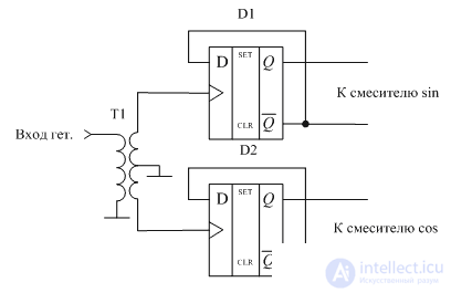
Figure 1 A diagram of the formation of output signals shifted in phase by 45 °
In this circuit, the voltage of the local oscillator is fed to the inputs of the trigger synchronization in antiphase. Therefore, the signals at the output of these triggers will be delayed relative to each other for a time equal to half the period of the input oscillation. Given that the triggers collected frequency divider circuit by two, the output oscillations will be shifted by a quarter period relative to each other. The shift of the periodic by a quarter period corresponds to a phase shift of 90 °.
Timing diagrams of the input signal of the local oscillator and signals generated at the output of the D1 and D2 flip-flops, corresponding to the scheme shown in Figure 4, are shown in Figure 2.
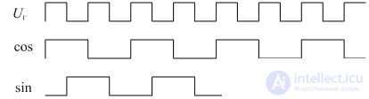
Figure 2 Timing diagram of the input local oscillator
and 45 ° out of phase output
As can be seen from this figure, at the output of the circuit from the input signal of the local oscillator, two signals are formed with a phase shift of 45 °.
Mixer chips, implemented according to the described principle, are produced by a number of companies. As an example, such chips as RF2713 RF2483 from RF Micro Devices, ADL5385 from Analog Devices, JCIQ-176D from Mini-Circuits can be cited. As an example, Figure 3 shows a block diagram of the ADL5385 chip from Analog Devices.
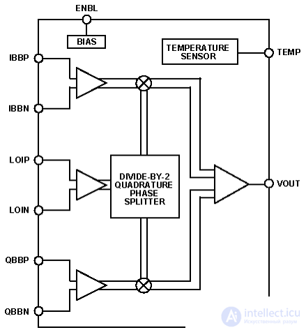
Figure 3 Circuit quadrature mixer ADL5385
The next step is to rotate the input signal by 90 °. This is usually done using an LC circuit. Of course, such a phase rotation is carried out only in a certain, rather narrow frequency range, however, the calculation of such devices is described in detail in a number of sources [1]. Considering that the range of received frequencies in mobile radio communication systems is quite narrow, the phase shifter circuit, which ensures the accuracy of phase rotation in a given range of about 1 °, can be quite simple. Suppression of the mirror channel at the same time can reach 40 dB. An example of a schematic diagram of a similar circuit of a power divider with a phase shift of the output signals by 90 ° is shown in Figure 4.
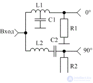
Figure 4 Schematic diagram of a power divider with a phase shift of the output signals by 90 °
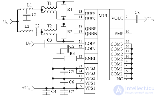
Figure 5 Schematic diagram of the mixer with the suppression of the mirror channel, assembled on the chip ADL5385

Comments
To leave a comment
Devices for the reception and processing of radio signals, Transmission, reception and processing of signals
Terms: Devices for the reception and processing of radio signals, Transmission, reception and processing of signals