Lecture
When discussing the types of modulation of the received signal used in terrestrial mobile radio systems, we found that amplitude modulation is not used in terrestrial radio communication systems. Amplitude modulation is used only in the frequency range 118 ... 136 MHz for communication with aircraft. In digital land mobile radio systems, including cellular communications, amplitude detectors (demodulators) in their pure form are not used. However, considering that almost all modern types of digital modulation contain an amplitude component, the amplitude detector is present in a modified form in a digital demodulator. Moreover, if we consider that the index of this parasitic modulation is not 30%, as in analog AM, but reaches 100%, then the complexity of the problems being solved increases by an order of magnitude.
Nevertheless, for the sake of completeness, let us consider the circuit of the amplitude detector, which makes it possible to transform the amplitudes of the high-frequency signal into low-frequency oscillations. Initially, the amplitude of the high-frequency oscillations was isolated on electronic devices with non-linear current-voltage characteristics, such as semiconductor diodes and transistors. The current-voltage characteristic (VAC) of a nonlinear element required for amplitude detection is shown in Figure 1.
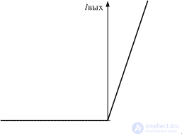
Figure 1. Volt-ampere characteristic of a nonlinear element necessary for detecting amplitude modulation
When an amplitude-modulated signal passes through an electronic device with a current-voltage characteristic, shown in Figure 1, a component appears in the output current, which is proportional to the amplitude of the input signal. The detection process on an electronic device with a similar current-voltage characteristic is illustrated in Figure 2.
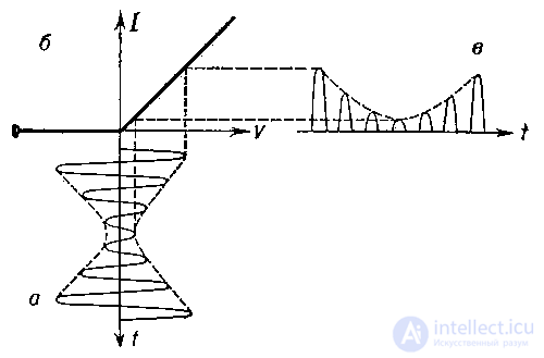
Figure 2. The process of detecting an amplitude modulated signal on a linear IVC
The actual current-voltage characteristics of nonlinear elements (such as semiconductor diodes or transistors) used in amplitude detectors are significantly different from the required IV. As a result, the amplitude response of the detector is obtained substantially nonlinear. In the current-voltage characteristics of these electronic devices, a step is observed in the region of 0.2 ... 0.8 V. The Schottky diodes and reversed diodes have the smallest step. Such diodes are used in amplitude demodulators. An example of the current-voltage characteristics of a Schottky semiconductor diode is shown in Figure 3.
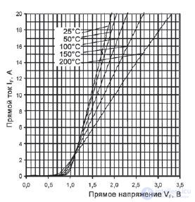
Figure 3. Volt-ampere characteristic of a semiconductor diode
An example of a circuit diagram of an amplitude detector made on a semiconductor diode is shown in Fig. 4. According to such circuits, AC voltmeter circuits are also constructed.
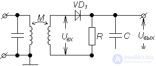
Figure 4. Schematic diagram of the amplitude detector
In this scheme, there is a significant influence of the detector output circuit on the detection characteristics, the inflection point of the current-voltage characteristic does not coincide with the zero value of the input signal voltage. All this leads to the fact that nonlinear distortions grow in the diode (or transistor) circuit of the amplitude detector with an increase in the modulation depth.
With a modulation depth of m = 0.5, nonlinear distortions reach 10%, and at m = 1, already 25%. This level of nonlinear distortion is unacceptable for modern equipment. The plot of nonlinear distortion versus modulation depth in a diode detector is shown in Figure 5.
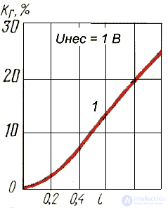
Figure 5. The dependence of nonlinear distortion on the modulation depth in the diode detector
Currently, synchronous detectors are commonly used as amplitude detectors. The main node of the synchronous detector is an analog multiplier (frequency mixer). In order for the multiplier to transfer the spectrum of the intermediate frequency signal to zero frequency (carried out the amplitude demodulation of the signal), it is necessary to apply the intermediate frequency voltage with the phase coinciding with the phase of the received signal to the second input of the analog multiplier. The principles of operation of the synchronous detector were discussed in detail when discussing the principles of operation of the direct conversion receiver.
In this scheme, it is very important that the signal arriving at one of the inputs of the multiplier assembled on transistors has a constant amplitude. Only in this case the signal at the output of the circuit will be proportional to the amplitude of the input signal. If the signal amplitude at both inputs of the multiplier changes, then we will get a quadratic amplitude detector, the output signal of which will be proportional not to the amplitude of the signal, but to its power.
To highlight the reference signal in modern radio receivers, an amplifier-limiter is used. At the output of the limiting amplifier, a signal of intermediate frequency with a rectangular shape and constant amplitude is formed. This signal is fed to one of the inputs of the signal multiplier. An unlimited intermediate frequency signal with amplitude modulation is applied to the second input of the signal multiplier. Its level is maintained at a constant level by an automatic gain control (AGC) system. A block diagram of such an amplitude detector is shown in Figure 6.
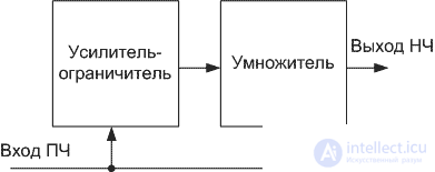
Figure 6. The block diagram of the amplitude detector, performed on an analog signal multiplier
Timing diagrams of the signals at the inputs and the output of the multiplier signals of the synchronous amplitude detector circuit are shown in Fig. 7.
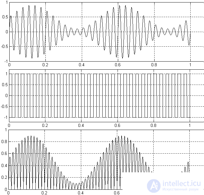
Figure 7. Timing diagrams of signals at the inputs and output of the multiplier
As can be seen from the above signal timing diagrams, there are no distortions at the output of the circuit. An example of a circuit diagram of an amplitude demodulator, made according to the synchronous detector circuit, is shown in Fig. 8.
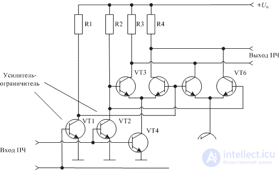
Figure 8. AM detector circuit on analog signal multiplier
In this amplitude detector circuit, an amplified signal with amplitude modulation is fed to one detector input, and the same signal, but limited in amplitude, to another input. As a result, the output of the input signal module (input signal amplitude) appears at the output of the circuit.
A similar scheme of amplitude detectors is often used in the composition of the scheme of modern radio receivers. As an example, Figure 9 shows the circuit for switching on the AM chip of the TDA1072 receiver.
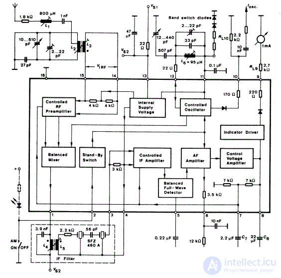
Figure 9. AM receiver circuit on a TDA1072 microcircuit
In this scheme, all the previously considered radio receiving units are located on a single crystal. At the input of the chip, the signal goes to the radio frequency amplifier, then it is fed to the balanced transistor mixer. From the output of the balanced mixer (pin 1), the signal through the piezoceramic filter of the intermediate frequency enters the input of the intermediate frequency amplifier (pins 3 and 4) connected to a balanced amplitude detector. After the demodulated signal is amplified by a low-frequency amplifier, the audio signal is removed from pin 6. To control the level of the received signal, an ameter meter can be connected to the ninth pin of the chip, which is converted into a level indicator using a RL9 resistor.

Comments
To leave a comment
Devices for the reception and processing of radio signals, Transmission, reception and processing of signals
Terms: Devices for the reception and processing of radio signals, Transmission, reception and processing of signals