Lecture
A radio receiving device (RPMU) is understood as a set of technical means designed to isolate radio signals with specific properties from a variety of electromagnetic fields *** present at the receiving site. The power of the useful signal may be an insignificant share of the total power of electromagnetic coli *** at the receiving point. RPMU is designed to separate the useful radio signal from a mixture of received signals and restore the transmitted message.
The main characteristics of the RPMU are largely determined by the structure of its construction. Currently, several principles are used for constructing an RPMU. Consider the two most common technologies for receiving radio signals.
The direct gain receiver circuit is shown in Figure 7.6. The receiver enters the entire set of signals induced in the antenna at the receiving point. Along with the useful signals, electromagnetic coli *** of other radio stations and other sources of radio emission are induced in the receiving antenna.
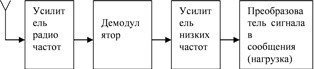
Fig. 7.6 Block diagram of a direct gain receiver
This structure of the receiving device is called a direct amplification circuit, because the received signal is amplified without additional transformations, at the same frequency at which it was radiated. When amplifying weak signals, the RF amplifier circuit becomes more complex and becomes multi-stage. The receiver circuit is very simple, but as the frequency of the received signal increases, it becomes more difficult to ensure good selectivity and sensitivity of the received signals, especially when the carrier frequency is tuned.
A more universal technique is reception with frequency conversion of received signals. A generalized block diagram of a superheterodyne receiver is shown in Figure 7.7.
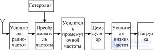
Fig. 7.7 Superheterodyne receiver block diagram
Superheterodyne receiver works as follows. The input of the radio frequency amplifier (RF amplifier) receives the entire set of signals and interference induced in the antenna at the receiving point. The radio frequency amplifier pre-selects (selects) signals with a frequency equal to the frequency of the useful (received) signal. The gain of the signals in the RF amplifier is usually small (in the simplest receivers at the radio frequency there is no gain at all).
The main amplification signal is received in the intermediate frequency amplifier (IFA), to the input of which the conversion products are received, obtained in the frequency converter when mixing the received signal from the RF amplifier output and the *** of the local oscillator. A frequency converter refers to a device by which the spectrum of the received signal, located in the region of the carrier frequency ***, called a radio frequency, is transferred to the carrier region *** with another frequency value, called an intermediate frequency. If the signal is converted without distortion, the spectrum of the received signal will move in parallel along the frequency axis by an amount equal to the local oscillator frequency, and the intermediate frequency f of the frequency converter will be equal to
f FC = | f С - f Г |, (7.1)
where f C and f G are the frequencies, respectively, of the signal and the local oscillator.With this frequency conversion, all information stored in the modulation parameters of the carrier frequency of the received signal is stored (only the value of the carrier frequency differs). The spectra of the received signal, the local oscillator and the intermediate frequency signal are shown in Figure 7.8.
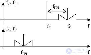
Fig. 7.8 Spectra of signals at superheterodyne reception
In a superheterodyne receiver, when changing the carrier frequency of the received signal, it is not necessary to make frequency controlled IFA circuits, since the signal gain in the IFCH is performed in a constant frequency range. When changing the frequency of the received signal, it is enough to change the frequency of the local oscillator so that relation (7.1) is satisfied. On the one hand, it simplifies the construction of the receiver as a whole, on the other hand, it allows to improve the characteristics of signal reception: selectivity and sensitivity. It should be noted that these advantages increase with increasing frequency of the received signal.
Subsequent receiver nodes: a demodulator, a low-frequency amplifier, and a load perform the same operations as similar cascades of a direct gain receiver.
The main disadvantage of a superheterodyne receiver is the ability to receive signals with a different carrier frequency (the so-called spurious reception channels). The relation (7.1) is fulfilled both at f ' C = f D + f FC , and at f С C = f D - f FC . This means that the receiver can simultaneously receive signals from two stations, both with frequency f' C , and and with a frequency of f ". One of these signals corresponds to the main receiving channel and is a useful signal; the second receiving channel is called a mirror channel. The signal of the mirror channel is an obstacle to the main reception channel, and measures are taken to reduce the influence of the mirror channel. To do this, in the input circuits of the receiver (up to the frequency converter) provide different conditions for the passage of signals with frequencies f ' C and f " C (try to isolate the useful signal and, conversely, suppress the image channel). The frequencies of these signals differ by a rather large amount (equal to twice intermediate frequency 2f IF ), therefore, the RF amplifier requirements in a superheterodyne receiver are not as rigid as in a direct gain receiver.
Radio receivers can be classified:
The main characteristics of radio receivers are sensitivity, selectivity, noise immunity.
Selectivity (selectivity) refers to the property of a receiving device, which allows to distinguish by certain attributes the useful radio signal from radio interference. In other words, selectivity is the ability of a radio receiver to select the desired signal from a variety of electromagnetic collars *** that are induced in a receiving antenna, weakening *** all other interfering signals.
Signals can be selected for various reasons. Spatial selectivity is associated with the direction of arrival of radio signals and is provided by the directivity characteristics of receiving antennas. Frequency selectivity characterizes the ability of a radio receiver to select from a set of signals and interference acting at the input, a signal corresponding to the frequency of tuning the radio receiver.
Receiver sensitivity reflects the ability of a radio receiver to receive weak radio signals. The problem of amplifying weak signals is that not only the useful signal is amplified in the receiver, but also interference. Moreover, due to the non-ideality of the characteristics of the receiver elements with increasing gain, the interference amplifies to a greater extent than the useful signal. The quality of the signal at the receiver output is estimated by the ratio of the signal power to the noise power (the so-called signal-to-noise ratio) at the receiver output. Under these conditions, the sensitivity of the receiver is defined as the minimum value of the EMF signal at the input of the receiving device, at which the signal-to-noise ratio at the output of the device does not exceed the allowable values.
Under noise immunity refers to the ability of the receiving device to operate with the required characteristics of the quality of reception in terms of interference.

Comments
To leave a comment
Devices for the reception and processing of radio signals, Transmission, reception and processing of signals
Terms: Devices for the reception and processing of radio signals, Transmission, reception and processing of signals