Lecture
For the emission and reception of electromagnetic collars that carry information, special radio devices are used, called antennas. The design and characteristics of the antennas depend on many factors, in particular, on the destination of the radio transmitting device, the range of working wavelengths, etc.
In the meter and decimeter wave bands, one of the common types of antennas is a symmetrical vibrator. Symmetrical vibrator consists of two identical segments of a conductor lying on the same line with a small gap, the value of which is much less than the length of the conductor (Fig. 7.1). The gap is provided for connecting the AC source. Symmetrical vibrators have the best characteristics, in which the length of each of the conductors is equal to a quarter of the wavelength of the radiated col ***. The dimensions of the antenna in this case are equal to half the wavelength, and this antenna is called a half-wave vibrator.
One of the most important characteristics of antennas is the radiation pattern. Under the antenna pattern understand the dependence of the power flux density on the direction of radiation during transmission. The diagram of the radiation pattern is a locus of points, the distance from which to the center of coordinates is proportional to the power flux density radiated in a given direction. The center of the antenna is placed in the center of coordinates. When receiving the radiation pattern characterizes the dependence of the induced emf on the direction of the spatial orientation of the antenna. One of the directivity characteristics is the directional coefficient D, defined as the ratio of the power flux density P MAX emitted in the direction of maximum radiation, to the power flux density P emitted by a point source of the same power in the same direction:
D = P MAX / P.
The directional diagram of a symmetric vibrator is shown in Figure 7.1, b. In the plane passing through the axis of the conductor, the directional pattern of a symmetric vibrator resembles a "eight". This means that in the direction of the axis “X” the density of the radiated power is maximum, and in the direction of the axis “Y” it is minimal. The directional properties of the symmetric vibrator are weakly expressed, and in a fairly wide sector of the φ directions, the flux density of the radiated power varies slightly.
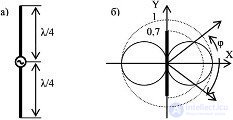
Fig. 7.1 Half-wave vibrator (a) and its radiation pattern (b)
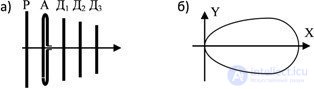
Fig. 7.2 Antenna of the “wave channel” type (a) and its radiation pattern (b)
The directional properties of the antennas can be used both to increase the communication range (in the direction of maximum radiation) and for selective reception in space (while various communication tools can work in different spatial sectors without interfering with each other).
In the antenna variants considered above, the longitudinal axis of the vibrator was located in a plane parallel to the surface of the earth. It is also possible variant of the vertical arrangement of the axis of the vibrator. In the relatively low frequency radio wave bands, the Earth is a good conductor of electric current and the vertical vibrator can be represented only by one half. The source of alternating current includes between the base of the vertical vibrator and the Earth (Fig.7.3).
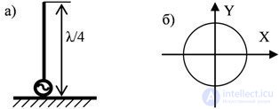
Fig. 7.3 Asymmetrical quarter-wave vibrator (a) and its radiation pattern in the horizontal plane (b)
Such an antenna is called an asymmetrical quarter-wave dipole antenna. In the case of a conducting Earth, a direct wave comes directly from the antenna and a wave reflected from the Earth at every point of the surrounding above-ground space. These waves will induce the same electromagnetic field as the field induced by a complete symmetric vibrator isolated from the Earth. The resulting electromagnetic field above the surface of the Earth will coincide with the field formed by a half-wave vibrator, but with a reduced power of half. The horizontal radiation pattern of such an antenna is a circle: transmission (reception) can be conducted from any direction without degrading performance. Such antennas are used not only in the range of meter waves, but also in the ranges of longer waves.
In the decimeter and centimeter wavelengths, waveguides (metal pipes of circular or rectangular cross-section) are used to transmit electromagnetic waves. The open end of such a waveguide is capable of radiating electromagnetic energy into open space. However, a sharp change in the propagation conditions of electromagnetic collars at the waveguide boundary — the open space causes poor radiator characteristics. To improve the directional properties of the antenna and match the characteristics of the propagation of the propagation medium, the waveguide is an open space that radiates the end of the waveguide as a horn (Fig. 7.4). The directivity characteristics of a horn antenna improve with an increase in the area of the radiating part of the horn, called the aperture of the antenna. Still, horn antennas are rarely used as a stand-alone device, and more often are elements of more complex antennas.
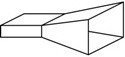
Fig. 7.4 Horn antenna
The directional properties of the antenna can be improved with a special-shaped mirror reflector. If a radiator is placed in the focus of a parabolic reflector, then the rays reflected from the mirror will be concentrated in a narrow sector of space (Fig.7.5). In this case, the aperture area of the antenna is determined by the dimensions of the reflector, and the directional properties of the antenna depend on the ratio of the diameter of the reflecting mirror and the wavelength of the radiated col ***.

Fig. 7.5 Mirror parabolic antenna
In addition to those considered in communication technology, other types of antennas are also used.
The electrical circuits by which radio signals are transmitted from the radio transmitter to the antenna or from the antenna to the radio receiver are called feeders. The design of the feeders depends on the operating frequency range, the power levels of the transmitted signals, operating conditions, etc.
In the long wavelength range, the feeders are in the form of wire lines. In the area of higher frequencies, coaxial cables are used: two conductors in the form of cylinders with combined axes of symmetry (coaxial - coaxial). The outer conductor of the coaxial cable (braid) is separated from the inner conductive core by the dielectric and is a good shield for currents flowing through the central conductor from external electromagnetic radiation. In the ultra-high frequency range, waveguides have the best characteristics for the transmission of electromagnetic energy: hollow metal pipes of circular or rectangular cross section.
An important role in the operation of antenna devices is played by the transmission line (feeder), which transfers energy from the generator to the antenna (in the transmitting mode) or from the antenna to the receiver (in the receive mode).
The main requirements for the feeder are reduced to its electro-tightness (the absence of radiation energy from the feeder) and low heat loss. In the transmitting mode, the impedance of the feeder must be matched with the input impedance of the antenna (which provides the traveling wave mode in the feeder) and with the output of the transmitter (for maximum power output). In the receiving mode, matching the receiver input with the feeder impedance in the last mode of the traveling wave, matching the feeder impedance with the load resistance is the condition of maximum power output to the load of the receiver. Depending on the range of radio waves, different types of feeders are used:
other

Comments
To leave a comment
Devices for the reception and processing of radio signals, Transmission, reception and processing of signals
Terms: Devices for the reception and processing of radio signals, Transmission, reception and processing of signals