Lecture
The successful development of radio communications is accompanied by an increase in the speeds and volumes of transmitted information. For the transmission of increasing information flows with low losses, signals with a wider band are used, which requires an expansion of the frequency range occupied by the communication system. In turn, the transmission of signals with a wider bandwidth requires a transition to higher carrier frequencies. Moreover, it is impossible to expand the operating frequency band of the communication systems in the already developed wavelengths due to tightness in the air. Historically, in the first place, the long-wave sections of the radio band were mastered, and areas with higher frequency signals were reserved for promising radio engineering systems, both by international agreements and national standards.
As a result, modern communication systems master the ranges of ever shorter waves. The advantages of ultrashort wave bands also include an insignificant level of atmospheric and industrial noise. In addition, broadband signals allow the use of advanced modulation and other signal processing techniques that provide the best characteristics of reception noise immunity. At the same time, it must be remembered that radio waves with a wavelength shorter than 10 meters can be effectively used only within the limits of direct visibility.
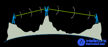
A compromise solution in the construction of broadband communication systems designed to work at long distances is the use of radio relay communication lines (RRL). Radio relay lines are a chain of repeaters that provide alternate transmission of radio signals between terminal stations. There are two types of radio-relay transmission systems (RRSP) - direct-of-sight RRSP, whose stations are located at a direct line of sight, and tropospheric RRSPs that use scattering and reflection of radio waves in the lower regions of the atmosphere with the relative position of stations far beyond the line of sight.
In the RRSP, a line of sight is suspended from high structures (masts, pylons, high-rise buildings, etc.) to increase the distance between the stations of the microwave relay lines of the antenna of the repeaters. In the conditions of the flat terrain, the elevation height of the antennas 60 ... 100 meters makes it possible to organize confident communication at distances of 40 ... 60 kilometers.
The chain of a radio relay line consists of three types of radio relay stations: terminal radio relay stations (ORS), intermediate radio relay stations (ORS), node radio relay stations (URS). The conventional radio relay link is schematically represented in Figure 8.1.
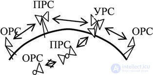
Fig. 8.1 Radio relay communication line
Intermediate radio-relay stations are designed to receive signals from the previous station of the radio-relay line, amplify these signals and radiate in the direction of the subsequent radio relay station.
At each intermediate radio relay station, two antennas are installed, which are oriented to adjacent RRSPs. Each of the antennas is transceiver, that is, it is used for both reception and transmission of signals. One of the advantages of the operation of the radio-relay communication line in the microwave spectrum is the possibility of using highly directional antennas with small dimensions. The small size of the antennas simplify their installation on high structures. The good directional properties of microwave antennas make it easier to meet the performance requirements of the transceiver path.
If the frequency of the emitted signal of the intermediate radio relay station were equal to the frequency of the received signal of the same ORS, there would be a danger of a powerful signal transmitted in the direction of the subsequent RRSP to the receiver of the same ORS receiving the signal from the opposite direction from the previous RRSP. This is explained by the fact that, despite the good directional properties of the transmitting and receiving antennas of the microwave range, it is still not possible to completely exclude the possibility of the powerful transmitter signal (even if weakened by directional antenna characteristics) entering the receiver with high sensitivity. Such unauthorized (parasitic) transmission of signals from the transmitter of an intermediate radio relay station to the receiver input of the same ORS is attempted to be reduced. Otherwise, the ORS may go into self-excitation mode and, instead of retransmitting received signals, the ORS transmitter will emit cola *** s that have no relation to the information transmitted over the X-ray radar.
One way to reduce the effect of a transmitter on the receiver’s performance of the same ORS is to emit the output signal of an ORS at a different frequency offset from the frequency of the received signal by an offset value equal to
f ADD = | f PRD - f PRM |, (8.1)
where f PFP is the frequency of the received signal; f Send - the frequency of the emitted signal. The value of f MDW is chosen from the condition of guaranteed exclusion of the mutual influence of signals at the selected frequencies.One chain of RRL transceivers forms a microwave simplex (i.e., designed to transmit signals in one direction) trunk. The structure of the simplex trunk with regard to the frequency distribution plan is shown in Figure 8.2.
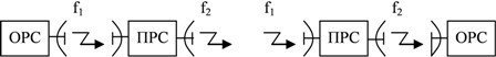
Fig. 8.2 Frequency distribution in the symbolic trunk of a radio relay line
Two simplex trunks, working in opposite directions, form a duplex microwave trunk. For signal transmission in the opposite direction, the same pair of frequencies as in the forward direction (two-frequency system) or another pair of frequencies (four-frequency system) can be used. The block diagram of a single-trunk duplex intermediate radio relay station is shown in Figure 8.3.
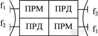
Fig. 8.3 Duplex ORS block diagram
To increase the capacity of the radio-relay line, several sets of transceiver equipment connected to a common antenna are installed at each radio relay station. Trunk microwave links can have up to eight duplex microwave trunks (6 ... 7 of them are working and 1 ... 2 are backup).
In addition to the LFS and the ORS, for the input to the radio relay line of additional information streams and the output from the RRL part of the transmitted information, nodal radio relay stations are used. In the nodal radio relay stations, as in the LFS, there is an equipment for converting telephone, radio and television signals into signals transmitted via the RRL, and equipment for inverse transformation. In addition, new radio relay lines (branches) may begin from hub radio relay stations.
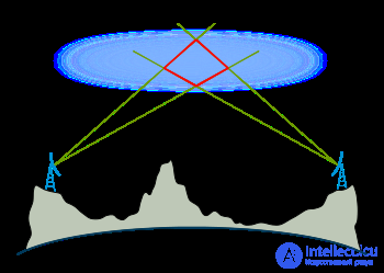
When designing radio relay lines, it is necessary to take into account possible changes in the propagation conditions of radio waves. So, with increased refraction (curvature of the direction of propagation of radio waves) signals can spread far beyond the horizon. Therefore, the collars emitted by a radio relay station with a frequency, for example, f1, can be received not only by a neighboring station, but also by a station separated from it after three flights. But for the last station this will be a spurious signal, since it should receive signals only from the nearest station. Unwanted signals from all other stations will cause reception degradation.
In order to eliminate such phenomena, repeaters of a radio-relay communication line are located not in a straight line, but in a zigzag manner, so that the main directions of the neighboring sections of the path using the same frequencies do not coincide. In this case, the directional properties of the antennas are used. Radio relay stations are spread from the general direction of the radio relay link so that the direction to the station, separated by three flights, corresponds to the minimum levels of the antenna pattern. Figure 8.4 shows three spans of a part of the RRL route. At the extreme spans used the same frequency. On such a path, even with strong refraction of radio waves, signals from stations with the numbers of ORS i and IRS i + 2 have practically no effect on each other. The figure shows that the antennas practically do not perceive radio waves coming from the direction lying on the line connecting these stations.
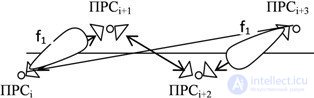
Fig. 8.4 Repeaters location scheme on the microwave path
Tropospheric radio relay transmission systems use local volumetric inhomogeneities of the atmosphere caused by various physical processes occurring in near-Earth space. These inhomogeneities are capable of reflecting and scattering electromagnetic waves as they propagate in the atmosphere. Since inhomogeneities are located at a considerable height, the radio waves scattered by them can propagate over large distances, which are much longer than the line of sight distance.
Due to the irregular structure of tropospheric irregularities, signals from the troposphere lines are subject to deep fading. This makes it difficult to transfer large amounts of information with good quality. Taking into account the above circumstances, tropospheric radio relay communication lines are beneficial to build in remote and remote areas with not too large amounts of transmitted information. In Figure 8.5. shows the route section of the radio relay link. At the same time, distances between stations can be selected up to several hundred kilometers, and the capacity of communication systems can be dozens of telephone channels.
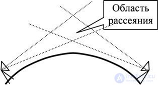
Fig. 8.5 Tropospheric RRSP
Radio-relay communication is one of the types of terrestrial radio communications, based on the repeated relay of radio signals [1] . Radio relay communication is usually carried out between stationary objects.
Historically, radio relay communication between stations was carried out using a chain of relay stations, which could be both active and passive.
A distinctive feature of radio relay communication from all other types of terrestrial radio communications is the use of narrowly directed antennas, as well as decimeter, centimeter or millimeter radiowaves.
In 1931, Andre Clavier, working in the French research unit of LCT at ITT, showed the possibility of organizing radio communications using ultrashort radio waves. During preliminary tests, on March 31, 1931, Klavir successfully transmitted and received telephone and telegraph messages using an experimental radio relay line operating at 1.67 GHz, placing two 3 m parabolic antennas on two opposite banks of the English Channel [2] . It is noteworthy that the installation sites of the antennas almost coincided with the take-off and landing sites of the historic flight over the English Channel Blouis. The success of the experiment, Andre Clavira, resulted in the further development of commercial radio-relay equipment. The first commercial radio-relay equipment was released by ITT, or rather its affiliated company STC, in 1934 and used amplitude modulation of a carrier band with a power of 0.5 Watt at a frequency of 1.724 and 1.764 GHz, obtained using a klystron.
The launch of the first commercial radio relay line took place on January 26, 1934. The line had a length of 56 km over the English Channel and connected the airports of Liempne in England and Saint-Englever in France. The built radio-relay line allowed transmitting one telephone and one telegraph channel simultaneously and was used to coordinate the air communication between London and Paris. In 1940, during the Second World War, the line was dismantled.
As a rule, radio relay communication is understood as radio relay communication of direct visibility.
When constructing radio-relay communication lines, the antennas of neighboring radio-relay stations are located within the line of sight [1] .
When constructing tropospheric radio relay communication lines, the effect of reflection of decimeter and centimeter radio waves from turbulent and layered inhomogeneities in the lower layers of the atmosphere — the troposphere — is used [3] .
The use of the effect of the long-range tropospheric propagation of radio waves of the VHF range allows you to organize communication over a distance of up to 300 km in the absence of direct visibility between the radio-relay stations. Communication range can be increased to 450 km with radio-relay stations located on natural elevations.
For tropospheric radio relay communication is characterized by a strong signal attenuation. Attenuation occurs as a signal propagates through the atmosphere, as well as due to scattering of a part of the signal upon reflection from the troposphere. Therefore, for stable radio communications, as a rule, transmitters with a power of up to 10 kW, antennas with a large aperture (up to 30 x 30 m²), which means high gain, as well as highly sensitive receivers with low-noise elements are used.
Also for tropospheric radio relay communication lines, the constant presence of fast, slow and selective fading of a radio signal is characteristic. Reducing the effect of fast fading on the received signal is achieved by using diversity frequency and spatial reception. Therefore, there are several receiving antennas on most of the tropospheric radio relay stations.
An example of the most famous and extensive tropospheric radio relay communication lines are:
Unlike radio relay stations, repeaters do not add additional information to the radio signal. Repeaters can be both passive and active.
Passive repeaters are a simple reflector of a radio signal without any receiving and transmitting equipment and, unlike active repeaters, they cannot amplify a useful signal or transfer it to another frequency. Passive radio relay transponders are used in the absence of direct visibility between radio relay stations; active - to increase the range of communication.
As a passive repeater, there can be both flat reflectors and antennas of radio relay communication connected by coaxial or waveguide inserts (so-called antennas connected back-to-back). Flat reflectors are usually used at small angles of reflection and have an efficiency close to 100%. However, as the angle of reflection increases, the efficiency of the flat reflector decreases. The advantage of flat reflectors is the possibility of using radio relay communication for relaying several frequency bands.
Antennas connected back-to-back are typically used at reflection angles close to 180 ° and have an efficiency of 50-60%. Such reflectors cannot be used to retransmit multiple frequency bands due to the limited capabilities of the antennas themselves.
For organization of radio communications, deci-, centi-millimeter and millimeter waves are used.
To ensure duplex communication, each frequency range is conventionally divided into two parts relative to the center frequency of the range. In each part of the range, frequency channels of a given band are allocated. Частотным каналам «нижней» части диапазона соответствуют определённые каналы «верхней» части диапазона, причём таким образом, что разница между центральными частотами каналов из «нижней» и «верхней» частей диапазона была всегда одна и та же для любых частотных каналов одного частотного диапазона.
В соответствии с рекомендацией ITU-R F.746 для радиорелейной связи прямой видимости утверждены следующие диапазоны частот:
| Диапазон (ГГц) | Границы диапазона (ГГц) | Ширина каналов (МГц) | Рекомнендации ITU-R | Решения ГКРЧ |
|---|---|---|---|---|
| 0.4 | 0,4061 - 0,430 0,41305 - 0,450 |
0,05, 0,1, 0,15, 0,2, 0,25, 0,6 0,25, 0,3, 0,5, 0,6, 0,75, 1, 1,75, 3,5 |
ITU-R F.1567 | |
| 1,4 | 1,350 - 1,530 | 0,25, 0,5, 1, 2, 3,5 | ITU-R F.1242 | |
| 2 | 1,427 - 2,690 | 0.5 | ITU-R F.701 | |
| 1,700 - 2,100 1,900 - 2,300 |
29 | ITU-R F.382 | ||
| 1,900 - 2,300 | 2,5, 3,5, 10, 14 | ITU-R F.1098 | ||
| 2,300 - 2,500 | 1, 2, 4, 14, 28 | ITU-R F.746 | ||
| 2,290 - 2,670 | 0,25, 0,5, 1, 1,75, 2, 2,5 3,5, 7, 14 | ITU-R F.1243 | ||
| 3.6 | 3,400 - 3,800 | 0,25, 25 | ITU-R F.1488 | |
| four | 3,800 - 4,200 3,700 - 4,200 |
29 28 |
ITU-R F.382 | Решение ГКРЧ № 09-08-05-1 |
| 3,600 - 4,200 | 10, 30, 40, 60, 80, 90 | ITU-R F.635 | ||
| U4 | 4,400 - 5,000 4,540 - 4,900 |
10, 28, 40, 60, 80 20, 40 |
ITU-R F.1099 | Решение ГКРЧ № 09-08-05-2 |
| L6 | 5,925 - 6,425 5,850 - 6,425 5,925 - 6,425 |
29,65 90 5, 10, 20, 28, 40, 60 |
ITU-R F.383 | Решение ГКРЧ № 10-07-02 |
| U6 | 6,425 - 7,110 | 3,5, 5, 7, 10, 14, 20, 30, 40, 80 | ITU-R F.384 | Решение ГКРЧ № 12-15-05-2 |
| 7 | ITU-R F.385 | |||
| eight | ITU-R F.386 | |||
| ten | 10,000 - 10,680 10,150 - 10,650 |
1,25, 3,5, 7, 14, 28 3,5, 7, 14, 28 |
ITU-R F.747 | |
| 10,150 - 10,650 | 28, 30 | ITU-R F.1568 | ||
| 10,500 - 10,680 10,550 - 10,680 |
3,5, 7 1,25, 2,5, 5 |
ITU-R F.747 | ||
| eleven | 10,700 - 11,700 | 5, 7, 10, 14, 20, 28, 40, 60, 80 | ITU-R F.387 | Решение ГКРЧ № 5/1,
Решение ГКРЧ 09-03-04-1 от 28.04.2009 |
| 12 | 11,700 - 12,500 12,200 - 12,700 |
19,18 20 |
ITU-R F.746 | |
| 13 | 12,750 - 13,250 | 3,5, 7, 14, 28 | ITU-R F.497 | Решение ГКРЧ 09-02-08 от 19.03.2009 [4] |
| 12,700 - 13,250 | 12,5, 25 | ITU-R F.746 | ||
| 14 | 14,250 - 14,500 | 3,5, 7, 14, 28 | ITU-R F.746 | |
| 15 | 14,400 - 15,350 14,500 - 15,350 |
3,5, 7, 14, 28, 56 2,5, 5, 10, 20, 30, 40, 50 |
ITU-R F.636 | Решение ГКРЧ № 08-23-09-001 |
| 18 | 17,700 - 19,700 17,700 - 19,700 17,700 - 19,700 18,580 - 19,160 |
7,5, 13,75, 27,5, 55, 110, 220 1,75, 3,5, 7 2,5, 5, 10, 20, 30, 40, 50 60 |
ITU-R F.595 | Решение ГКРЧ № 07-21-02-001 |
| 23 | 21,200 - 23,600 22,000 - 23,600 |
2,5, 3,5 - 112 3,5 - 112 |
ITU-R F.637 | Решение ГКРЧ № 06-16-04-001 |
| 27 | 24,250 - 25,250 25,250 - 27,500 25,270 - 26,980 24,500 - 26,500 27,500 - 29,500 |
2,5, 3,5, 40 2,5, 3,5 60 3,5 - 112 2,5, 3,5 - 112 |
ITU-R F.748 | Решение ГКРЧ № 09-03-04-2 |
| 31 | 31.000 - 31,300 | 3,5, 7, 14, 25, 28, 50 | ITU-R F.746 | |
| 32 | 31,800 - 33,400 | 3,5, 7, 14, 28, 56, 112 | ITU-R F.1520 | |
| 38 | 36,000 - 40,500 36,000 - 37,000 37,000 - 39,500 38,600 - 39,480 38,600 - 40,000 39,500 - 40,500 |
2,5, 3,5 3,5 - 112 3,5, 7, 14, 28, 56, 112 60 50 3,5 - 112 |
ITU-R F.749 | Решение ГКРЧ № 06-14-02-001 |
| 42 | 40,500 - 43,500 | 7, 14, 28, 56, 112 | ITU-R F.2005 | Решение ГКРЧ № 08-23-04-001 |
| 52 | 51,400 - 52,600 | 3,5, 7, 14, 28, 56 | ITU-R F.1496 | |
| 57 | 55,7800 - 57,000 57,000 - 59,000 |
3,5, 7, 14, 28, 56 50, 100 |
ITU-R F.1497 | Решение ГКРЧ № 06-13-04-001 |
| 70/80 | 71,000 - 76,000 / 81,000 - 86,000 | 125, N x 250 | ITU-R F.2006 | Решение ГКРЧ № 10-07-04-1 |
| 94 | 92,000 - 94,000 / 94,100 - 95,000 | 50, 100, N x 100 | ITU-R F.2004 | Решение ГКРЧ № 10-07-04-2 |
Частотные диапазоны от 2 ГГц до 38 ГГц относятся к «классическим» радиорелейным частотным диапазонам. Законы распространения и ослабления радиоволн, а также механизмы появления многолучевого распространения в данных диапазонах хорошо изучены и накоплена большая статистика использования радиорелейных линий связи. Для одного частотного канала «классического» радиорелейного частотного диапазон выделяется полоса частот не более 28 МГц или 56 МГц.
Диапазоны от 38 ГГц до 92 ГГц для радиорелейной связи выделятся недавно и являются более новыми. Несмотря на это данные диапазоны считаются перспективными с точки зрения увеличения пропускной способности радиорелейных линий связи, так как в данных диапазонах возможно выделение более широких частотных каналов.
Одними из особенностей использования радиорелейных линий связи является:
Методы резервирования радиорелейной связи можно разделить
Метод «горячего» резерва основывается на введении избыточности в аппаратуру радиорелейных станций. «Горячее» резервирование направлено на повышение надёжности аппаратуры и не может повлиять на характеристики радиосигнала в канале связи.
Метод частотного разнесенного приёма направлен на устранение частотно-селективых замираний в канале связи.
Метод пространственного разнесения применяется для устранения замираний, возникающих в следствие многолучевого распространения радиоволн в канале связи. Метод пространственного разнесения чаще всего используется при строительстве радиорелейных линий связи, проходящими на поверхностями с коэффициентом отражения близким к 1 (водная поверхность, болота, сельскохозяйственные поля).
Одним из недостатков поляризационного разнесённого приема является необходимость использования более дорогостоящих двухполяризационных антенн.
Наиболее надёжным методом резервирования является построения радиорелейных линий связи по кольцевой топологии.
Из всех видов радиосвязи радиорелейная связь обеспечивает наибольшее отношение сигнал/шум на входе приёмника при заданной вероятности ошибки. Именно поэтому при необходимости организации надёжной радиосвязи между двумя объектами чаще всего используются радиорелейные линии связи.
Исторически радиорелейные линии связи использовались для организации каналов связи телевизионного и радиовещания, а также для связи телеграфных и телефонных станций на территории со слабо развитой инфраструктурой.
Радиорелейные линии связи применяются при строительстве и обслуживании нефте- и газопроводов в качестве линий связи для передачи телеметрической информации. В настоящее время, в некоторых регионах, РРЛ испульзуется как резерв, а основную работу выполняет оптический кабель, проложенный параллельно магистрального трубопровода. В случае порыва оптического кабеля, всю нагрузку на себя берет РРЛ.
Радиорелейная связь находит применение в организации каналов связи между различными элементами сотовой сети, особенно в местах со слабо развитой инфраструктурой.
Современные радиорелейные линии связи способны обеспечить передачу больших объёмов информации от базовых станций 2G, 3G и 4G к основным элементам опорной сети сотовой связи.
At frequencies up to 12 GHz, precipitation in the form of rain or snow has little effect on the operation of radio relay communication lines.
In real conditions, the atmosphere has its own refractive index of radio waves, and the atmosphere is not a homogeneous medium, so the refractive index is different at different heights from the earth's surface.

Comments
To leave a comment
Devices for the reception and processing of radio signals, Transmission, reception and processing of signals
Terms: Devices for the reception and processing of radio signals, Transmission, reception and processing of signals