Lecture
A phase detector is a device that compares the phases of two signals of equal or close frequencies. The phase detector generates a voltage proportional to the phase difference.
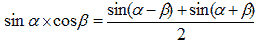
To determine the phase of an unknown oscillation, a reference point is required which will determine the origin of coordinates. Typically, such a reference point is the reference sinusoidal oscillation generated by a local oscillator (local oscillator). In this case, to isolate the phase, you can use the trigonometric identity:
 (one)
(one)
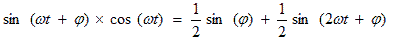
Under the condition of equality of the frequencies of the received signal and the local oscillator, the formula is converted to the form:
 (2)
(2)
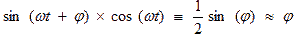
A voltage with a doubled frequency of the received signal (doubled intermediate frequency) at the output of the phase detector is easily suppressed by a low-pass filter and is not taken into account in further analysis:
 (3)
(3)
Given that the sine of a small angle is equal to the value of the angle itself, a voltage proportional to the phase of the received signal is present at the output of the analog signal multiplier. In other words, an analog signal multiplier can act as a phase detector, to one of the inputs of which a generator is connected with a frequency equal to the frequency of the received signal.
Unfortunately, from the same voltage formula at the output of the signal multiplier, the dependence of the output voltage on the amplitude of the input signal and the local oscillator signal (local oscillator) is visible. Therefore, before detecting a phase-modulated signal in a phase detector, the voltage of the input signal should be limited in amplitude.
In a number of phase detector circuits, as a result of a limitation or for a number of other reasons (frequency synthesizer, clock frequency multiplier), signals with logic levels are used. In this case, it is possible to use an "exclusive or" scheme as a digital phase detector.
The block diagram of the phase detector, implemented according to the principle described above, is shown in Figure 1.
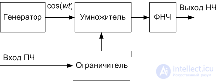
Figure 1. Block diagram of the phase detector
The voltage waveform at the output of the amplitude limiter approaches a square waveform with a duty cycle equal to two. The voltage (or current) at the output of the local generator (local oscillator) is also trying to get a rectangular shape. For a more accurate formation of a rectangular signal of a local oscillator with equal duration of a positive and negative value, a generator with a double frequency is often used. Then lower it on a binary divider (T-trigger). As a result, formula (3) is converted to the following form:
 (four)
The linear portion of the transfer characteristic of the phase detector as a result of the application of rectangular oscillations expands to the range  . An example of the transfer characteristic of the AD9901 phase detector is shown in Figure 2.
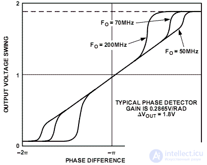
Figure 2. The transfer characteristic of the phase detector AD9901
The deviation of the transfer characteristic from the linear law in the chip is caused by its final speed.

Comments
To leave a comment
Devices for the reception and processing of radio signals, Transmission, reception and processing of signals
Terms: Devices for the reception and processing of radio signals, Transmission, reception and processing of signals