Schematic diagrams.
Practically, three types of circuits with autotransformer coupling with antenna are used in the input devices of receivers: autotransformer circuit, dual autotransformer circuit, and circuit with series connection of inductance. In the first two schemes, the autotransformer connection of the antenna or feeder is made in the inductive, and in the third scheme - in the capacitive branch of the kennel. In all schemes, parallel circuits are used as a frequency-selection system. 
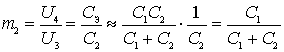
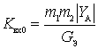
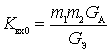
a) In the autotransformer circuit, the necessary degree of communication with the antenna is carried out by choosing the transformation ratio 
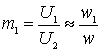 ,
,
 .
.
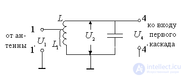
Figure 8.3.
The inclusion on the input side of the first cascade is complete, i.e. transformation ratio . In this case, the input active conductivity and the input capacitance of the first cascade of the receiver is fully connected to the circuit.
b) In the dual autotransformer circuit, the necessary degree of communication with the antenna is carried out, as in the previous case, by choosing the transformation ratio (inclusion)  . In order to reduce the input active and capacitive conductances into the circuit, an incomplete connection of the input of the first cascade to the circuit is used, i.e.
  .
.
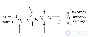
Figure 8.4.
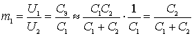
Incomplete connection of the circuit with the first stage can be implemented in the form of an autotransformer or transformer circuit or by communication through a capacitive divider. In an autotransformer or dual autotransformer circuit, the necessary transformation ratios are provided by tapping from a certain part of the turns of the inductance L of the circuit. With a known approximation, transformation ratios  and
and  can be determined from the ratios:
;  because
  .
.
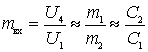
The overall transformation ratio of the input device can be represented as:
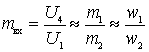 ;
;
Where  ,
,  ,
,  , - the number of turns in the inductor L or its parts
  and
and  .
.
Selection of ratios and In the scheme, you can make the necessary degree of connection with the antenna, in particular, the chosen mode of matching or mismatch.
c) In a circuit with a series connection of inductance, double transformation is carried out in the capacitive branch of the circuit.
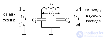
Figure 8.5.
The circuit is used at frequencies above 200-300 MHz, when the loop inductor degenerates into one turn and the transformation in the inductive branch becomes practically difficult to implement.
The equivalent circuit of the input device with a series connection of inductance is as follows:
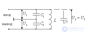
Figure 8.6.
The diagram shows that the antenna is connected to a capacitor  , and the input to the input of the first stage voltage is removed from the capacitor
  . Tank sizes and take into account the parasitic capacitance introduced respectively by the antenna and the input of the first stage. The capacitive branch of the circuit consists of series-connected containers and and parallel connected parasitic capacitance
  loop inductors, i.e. total contour capacity:
 .
.
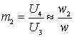
Transformation ratios, if we ignore the relatively small capacity , respectively, will be equal to:
 ;
;
 .
.
The overall transformation ratio in the input device, if the losses in the circuit itself are small, compared to the insertion, matters
 .
.
It follows that the selection of the relationship and You can realize the necessary connection with the antenna, in particular, the selected mode of matching or mismatch.
Equivalent scheme.
From the above consideration it follows that all three autotransformer circuits are special cases of the dual autotransformer circuit. The common circuit for all these types of input devices is as follows:
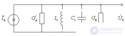
Figure 8.7.
In this diagram, the EMF source is presented in the form of a current generator.  with internal resistance
  . Since the antenna is tuned,
The resulting capacitance of the circuit takes into account the capacitance of the circuit itself and the containers introduced from the first stage.
a) for autotransformer circuit
 ;
;
b) for dual autotransformer circuit
 ;
;
c) for a circuit with sequential inductance
.
The resulting capacitance of the circuit should be as small as possible. The inductance of the circuit is selected from the condition of providing resonance at a given frequency  input device settings.
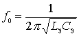 .
.
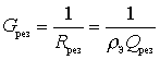
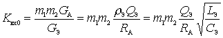
Load conductance is defined as
 .
.
Input device parameters.
The input device parameters are determined by the formulas obtained for the generalized single-loop input device, taking into account the knowledge of the transformation ratios and .
Resonance gain
 .
.
For tuned antenna  - active conductivity of the antenna.
Then
 .
.
Result Loop Loop
 .
.
Where ;
 ;
;
 .
.
Trace the nature of the change  on frequency . For this expression for we write in the following form:
 .
.
In autotransformer circuits, the coefficients and practically independent of frequency. If we assume that within the subrange does not significantly change the quality factor  and antenna impedance, i.e.
 ,
,  ,
,
then when rebuilding capacity grows with
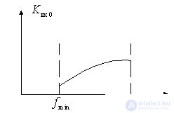
Figure 8.8.
Autotransformer circuits are simpler to manufacture and customize than transformer circuits. However, in these schemes it is difficult to implement small values of transformation ratios (inclusions), especially when coordinated with feeders with low wave resistance. When the loop is rebuilt by the capacitor and the capacitance in the autotransformer circuit, only increasing character can be obtained from .

Comments
To leave a comment
Devices for the reception and processing of radio signals, Transmission, reception and processing of signals
Terms: Devices for the reception and processing of radio signals, Transmission, reception and processing of signals