Lecture
Mobile systems with one base station, which provides system operation throughout the service area (called radial), have two major drawbacks. First, with a large distance from the base station, the signal to the mobile station comes with a large attenuation. This makes it necessary to increase the power of radio transmitters and the sensitivity of radio receivers, which, in turn, causes an undesirable increase in the weight and size of the mobile station and shorten the cycle of its power source. Secondly, an increase in the number of subscribers served leads to a proportional increase in the required radio channels. With a shortage of frequency resource, this hinders the further development of the system.
In cellular communication systems, the entire serviced territory is divided into relatively small zones (cells). The best shape of such a zone has the shape of a regular hexagon (with this shape, the centers of neighboring cells are at the same distance from each other, and at any point on the border between neighboring cells, the signals from the corresponding base stations will arrive at the same level). The organization of the communication system in this case resembles the pattern of combs in a beehive, and such systems are called cellular (Fig.10.5).
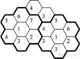
Fig. 10.5 Structure of the cellular system
The base station antenna generally has a circular pattern. The power of the radio transmitter is selected from the condition of stable reception of signals in the entire cell. In general, on the territory of the neighboring cell, the signal has a non-zero value, therefore it can disrupt the normal operation of the radio equipment of the neighboring cell.
To reduce the mutual influence of the signals of the stations of neighboring cells, the frequencies of the radio channels of each cell are chosen according to a certain rule, and base stations with the same set of frequencies are spread by a guard interval beyond which the mutual influence of neighboring stations is negligible. To this end, base stations with a different set of operating frequencies are placed between base stations with the same frequency sets. A group of neighboring cells with different sets of frequencies form clusters in which all the working frequencies allocated to a given communication system are represented, and none of the frequencies in the full set is repeated. The full set of frequencies determines the dimension of the cluster.
In Figure 10.5, bold lines indicate clusters with the number of frequencies in the set equal to 7 (in practice, clusters are formed with a different number of frequencies). As a result, the entire service area is covered by a network of clusters, and each cluster uses 7 different frequencies (7 sets of different frequencies). Thus, in the serviced territory, 7 working frequencies allocated in this mobile communication system will be repeated as many times as the clusters form this system. And at the same time, the operation of stations at these frequencies in neighboring clusters will not cause a negative influence on each other. The method of frequency reuse allows to increase the number of subscribers served by the same amount of time.
Other measures are also being taken to further increase the number of clients served: reduce the cell radius in areas with a high concentration of mobile stations (supermarkets, airports, etc.). The typical cell size of a cellular mobile communication is several kilometers, cells measuring several hundred meters are called micro-cells, and cells measuring several tens of meters are pico-cells. For the same purpose, base stations use not one antenna with a circular radiation pattern, but several antennas with sector radiation patterns. In this case, the frequency reuse structure is more complex, but one frequency within one cluster can be used twice.
The block diagram of the cellular mobile communication system is presented in Figure 10.6.
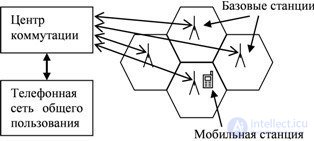
Fig. 10.6 Block diagram of a cellular mobile radio system
Serviced area is divided into cells of the appropriate size. Approximately in the center of each cell, a base station is installed, which includes a transceiver device, an antenna-feeder device to form radio channels with mobile stations, and a control device (controller). The controller is designed to handle the mobile station's connections with the rest of the network. The mobile station can be located anywhere in the service area. The core of the system is the switching center to which each base station is connected by a special communication channel. The switching center also has access to the public telephone network and manages the establishment of connections, both between mobile stations and fixed phones.
In cellular systems, two types of communication channels can be established between a mobile station and a base station: control channels and information channels. The control channels are designed to exchange information related to the execution of the service request, calling the subscriber and establishing a connection between the calling and called subscriber. In turn, the control channel is divided into direct (from the base station) and reverse (from the mobile station). Information channels are designed to transmit voice or data between users.
The mobile station is constantly in standby mode on the call channel. The mobile station is initialized (when turned on) in advance: the mobile station scans the direct control channels of the neighboring base stations and selects the channel with the strongest signal (the nearest base station). The mobile station transmits its personal data to the switching center via a free reverse control channel, which is used to register the mobile station. Service information exchange operations with the base station are regularly repeated as long as the mobile station is turned on. In addition, the mobile station monitors the call signals.
In mobile communication systems, continuity of communication should be ensured when a subscriber moves from one cell to another. To do this, the mobile station constantly scans the control channels of neighboring base stations and selects the channel with the strongest signal. This allows you to monitor the movement of the mobile station, and if the mobile station enters another cell, a new base station is selected. Such an organization of communication of mobile stations is called a relay transmission, which is performed without interrupting the communication session, and in modern systems and imperceptibly for subscribers.
A request for a communication session from a mobile station is sent over a free control channel through a base station to a switching center. According to the registration data of mobile stations, the switching center determines the base station, in the coverage area of which the called mobile station is currently located, and sends it the number of the called subscriber. The base station forwards the direct control channel sends a call to the called subscriber.
The called station in the forward control channel service information stream recognizes the message addressed to it by the number and sends the response to the base station. According to this answer, the switching center establishes a communication channel between base stations serving the calling and called subscribers, as well as information channels within the cell, through which the base and mobile stations exchange information. The corresponding signals from the switching center are transmitted to the base stations and then to the mobile stations, as a result of which the mobile stations will switch to the dedicated information channels. If during a communication session the mobile station moves into the coverage area of another base station, then under the control of the switching center the old channel is replaced with a new one without interrupting the communication session.
Despite the short historical period of development, mobile cellular communication went through several stages.
The first generation of cellular communication systems used analog signals for voice transmission. Of the various mobile communication systems, AMPS (North America), NMT (Northern Europe) are the most common. The same systems are used in Russia. Thus, the NMT (Nordic Mobile Telephone System) system uses the frequency range 453 ... 467 MHz (NMT-450) with a duplex spacing of 10 MHz and 890 ... 960 MHz with a spacing of 45 MHz. Each channel in both systems occupies a 25 kHz band with frequency modulated signals.
First-generation analog mobile communication systems use different standards, which makes them difficult to use together, have poor communication quality, and do not allow encryption of transmitted messages.
Second generation mobile communication systems use digital transmission methods. The most widespread are the European GSM standard, the American D-AMPS and the Japanese JDC. In Russia, the GSM standard has been adopted as the federal standard.
The GSM-900 system (Global System for Mobile communications) operates in the 890 ... 915 MHz band for transmitting signals from the mobile station and in the 935 ... 960 MHz band for transmitting from the base station. Each of these bands is divided into 124 frequency channels with spacing between 200 kHz. The time and frequency structure of the GSM signal is shown in Figure 10.7. In each frequency channel, the signals of 8 subscribers are alternately transmitted during a frame, that is, both frequency and time division channels are used.
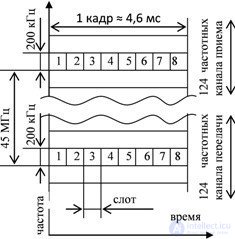
Fig. 10.7 GSM time and frequency structure
The structure of the channel interval of the GSM standard is shown in Figure 10.8. Encrypted information bits are transmitted in two portions of 57 bits. The training sequence (a known combination of bits that is different for each cell) is used to tune the receiver parameters for the received signal. In each channel interval, service signals (synchronization, control, etc.) are transmitted, protective bits are provided to prevent the penetration of signals from adjacent channels.
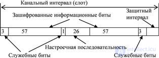
Fig. 10.8 The structure of the channel interval of the GSM standard
In the GSM system, when the distance between the base station and the mobile station changes, the base station transmits control signals to the mobile station to temporarily shift the signals transmitted by the mobile station. This eliminates the signals of different mobile stations located at different distances from the base station on the common time intervals. When the range is changed, control signals are also sent to the mobile station, which regulate the power of the emitted signal.
Under urban conditions, signal propagation is accompanied by numerous reflections and re-radiations. As a result, not only the main signal arrives at the receiving point, but also copies of this signal with different amplitudes and time delays. Ultimately, multipath propagation leads to signal fading. To combat fading in the GSM system, slow frequency jumps are used: the message transmitted to the subscriber in the allotted time interval is transmitted on a different frequency in each frame

Comments
To leave a comment
Devices for the reception and processing of radio signals, Transmission, reception and processing of signals
Terms: Devices for the reception and processing of radio signals, Transmission, reception and processing of signals