Lecture
1) By operating frequency range and tuning method:
- with a smooth restructuring;
- with discrete rearrangement.
2) By type of election system:
- with one resonant circuit;
- with two or more resonant circuits;
- with special band-pass filters.
3) By the type of communication of the electoral system with the antenna:
a) with transformer coupling:
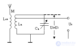
Figure 5.2.
An input device with a transformer coupling is used for communication with unbalanced and symmetric, with unconfigured and tuned antennas. Communication with the electoral system may vary widely. The transmission coefficient may be given the necessary nature of the change within the sub-band: increasing or decreasing. Schematically and constructively, this kind of communication is somewhat more complicated than the others. Loop Inductor  using coupling coil
  transformer connected to the antenna. Degree of coupling between coupling coils and contour characterized by the coefficient of mutual induction M.
 .
.
b) with autotransformer connection:
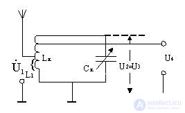
Figure 5.3.
An input device with an auto-transformer connection is typically used to communicate with unbalanced, tuned antennas. Opportunities to reduce communication are limited. The nature of the change of the transmission coefficient over the range cannot vary. Schematically and structurally, the input device is relatively simple. In autotransformer coupling, the antenna is connected to the resonant system by connecting it to a part of the turns of the inductance coil of the electoral system. The degree of connection is quite accurately determined by the ratio of inductance  between the tap and the casing and the total inductance input circuit;
c) with capacitive coupling:
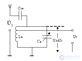
Figure 5.4.
A capacitively coupled input device is typically used to communicate with unbalanced, unconfigured antennas. This input device is the simplest according to the scheme and according to the possibilities of changing the degree of connection with the antenna. However, its parameters vary dramatically over the frequency range.
The capacitive coupling electoral system connects to the antenna through a capacitor  . The degree of connection with the antenna depends mainly on the ratio of capacities and capacitor circuit
  ;
;
g) with a combined link:
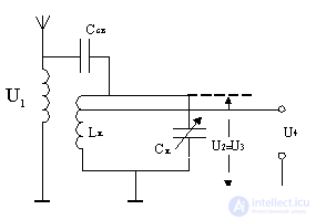
Figure 5.5.
The use of combined communication allows to reduce the non-uniformity of the transmission coefficient in radio receivers with a high subband overlap ratio.
4) According to the type of communication of the electoral system with the input of the amplifier-converter cascade:
a) with full inclusion  :
:
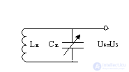
Figure 5.6.
b) with autotransformer connection 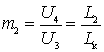
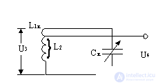
Figure 5.7.
c) with transformer coupling 
Figure 5.8.
d) with communication through capacitive divider
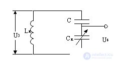
Figure 5.9.
When fully connected, the input resistance and the input capacitance of the first cascade are directly connected to the electoral system. With incomplete switching on, the input effect can be greatly reduced.
5) By design:
a) using elements with lumped parameters - in the range of long, medium, short and meter waves;
b) using segments of long lines in the form of coaxial and strip resonators - in the range of decimeter waves;
c) using volume resonators - in the range of centimeter and less waves.

Comments
To leave a comment
Devices for the reception and processing of radio signals, Transmission, reception and processing of signals
Terms: Devices for the reception and processing of radio signals, Transmission, reception and processing of signals