Lecture
Interference is called an extraneous electric ring *** that interferes with the normal reception of signals. The cause and sources of interference can be various factors, and interference can be classified according to various criteria.
Depending on the place of origin, extraneous electric rings can be divided into external and internal interference. Internal interference occurs in the nodes of the equipment and paths of communication systems. External interference is due to the effect of interference sources external to the communication system and not related to its operation.
By the degree of possibility of eliminating interference, the latter can be classified into disposable and non-removable interference.
Fundamentally unremovable type of interference is internal interference. They appear immediately after switching on the equipment. By the nature of the occurrence, internal disturbances are divided into thermal and shot noise. Thermal noise is caused by the chaotic movement of electrons in conductors and is inherent in almost all elements of the electrical circuit. One of the most effective methods of reducing this component of interference is to reduce the temperature of the elements of this circuit. Fractional noise is characteristic of the so-called active electrical circuit devices (bipolar and field-effect transistors, electron-vacuum and gas-discharge lamps, and so on) and occur in amplifiers, transducers, modulators, etc. To reduce the fraction of shotgun noise, devices with improved noise characteristics are used.
The noise of the receiving antenna and the receiver input stages have the greatest influence on the characteristics of communication. This is due to the fact that the noises of the cascades, located closer to the input of the receiver, receive the same gain as the received signals. The noise of the subsequent stages is amplified to a lesser extent, so their contribution to the resulting noise at the receiver output is significantly less than the noise coming from the input devices.
The internal noise of electronic devices manifests itself in all frequency bands used in radio communications. The share of internal noise increases with increasing frequency, and in the ultra-high frequency range, their value becomes predominant, since the share of other types of interference can be significantly reduced. External interference is caused by the action of interference sources that are not caused by the operation of this communication channel. At the place of occurrence of this interference can be divided into the following components.
Atmospheric interference is caused by electrical phenomena in the atmosphere (thunderstorms, lightning, etc.). The spectrum of atmospheric noise is concentrated mainly in the low-frequency region, and atmospheric interference has the greatest effect on the radio communications of the long-wavelength range.
Cosmic noise caused by radio emission of any objects in space, for example, any constellations. The sun is also a source of radiation in the radio. The solar radiation noise characteristics, in particular, are affected by sunspots. Cosmic noise has the greatest impact on satellite communication systems, especially when the directions of reception of useful signals and sources of noise emissions coincide.
Industrial interference is caused by unintended electromagnetic radiation from electrical or electronic equipment. Among them may be installations of industrial, transport, medical, scientific purposes. The source of this radiation is usually the circuit in which the switching of strong currents, welding machines, collector motors, etc. The level of such unplanned emissions is limited by standards for maximum permissible radiation levels. At the places of occurrence of such interference, measures are taken to reduce the radiation level.
The spectrum of industrial noise is lowered to the low-frequency range, and the level of frequency components of the interference decreases with increasing frequency. At the same time, modern electronic devices that are not designed to work with radio waves are sources of radio emission. First of all it concerns digital devices, for example, computers. The emission spectrum of such devices is determined by the speed of its main processes and spreads to the region of high frequencies.
Another source of radio interference is radioactive spurious emissions. The reason for their occurrence is as follows. Each radiocommunication device for its normal functioning in the general frequency range is allocated a certain frequency band. This frequency band is determined by government agencies in the light of international agreements. These bodies determine not only the range of frequencies permitted for operation, but also determine the levels of out-of-band emission, that is, those levels of spurious emission that can be generated by this device outside the band of allowed frequencies.
In real devices, spurious emission almost always exists and can affect the radio characteristics of other systems. For example, let the receiver receive weak signals with a frequency f1, and a radio source is operating nearby with a frequency equal to f1 / 2. If the level of suppression of the second harmonic of this source of radio signals is insufficient, then the spurious emission of the second harmonic emitted by this source and equal to 2 * f1 / 2 = f1 will interfere with the reception of other signals with a frequency f1.
Interference can be classified by other characteristics.
For example, by the duration of the existence of interference, they can be divided into pulsed and continuous interference.
By the nature of the energy distribution of interference in the frequency range is divided concentrated on the spectrum and distributed interference.
By the nature of the interaction with the signal, interference can be divided into additive and multiplicative interference. With additive interference, the result of the interaction of the signal s (t) and the interference n (t) is their sum
x (t) = s (t) + n (t); (4.15)
in case of multiplicative interference, the result of processing the received signals is affected by their product s (t) * n (t).
Anti-jamming techniques are to ensure that the level of the signal at the receiving location, which would provide the required quality of the received signal. One of the most important characteristics of the received signal is the ratio of signal power to noise power. This parameter in radio engineering is called signal / noise ratio. This ratio at the receiving point can be increased in various ways, for example, by increasing the transmitter power of the communication system, using a transmitting or receiving antenna with directional properties (if the operating conditions for this communication system permit). The signal-to-noise ratio can be increased by reducing the noise level. For example, the share of internal noise can be reduced by using low-noise amplifiers in the input stages of the receiver.
Other methods for improving the quality of received signals are associated with the use of complex signals and methods for their processing that provide an increase in the signal-to-noise ratio at the output of the receiving device.
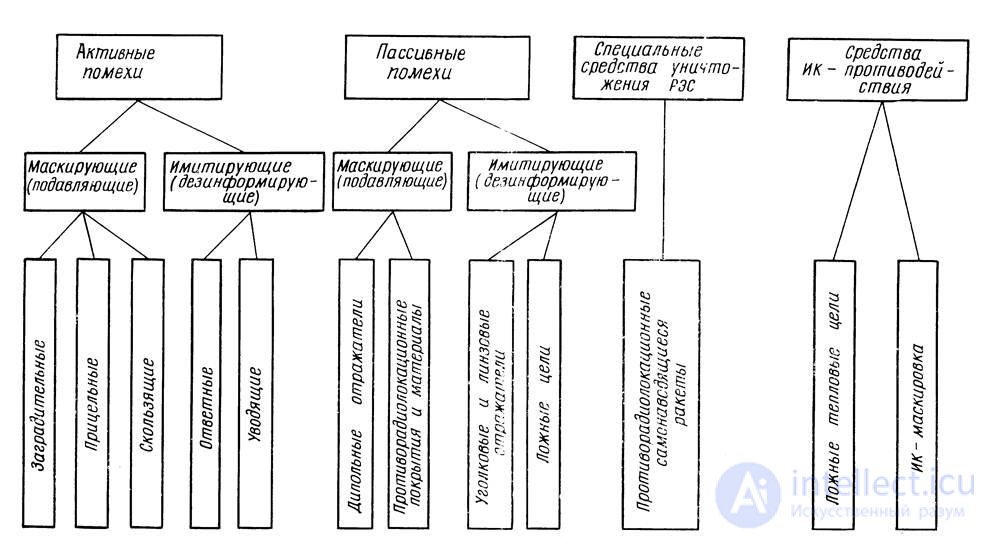
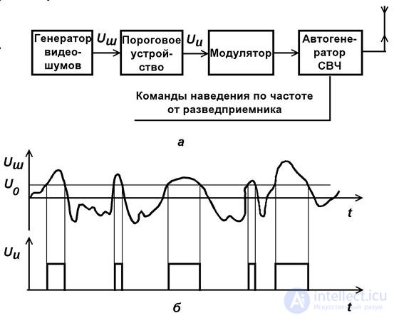
AIPs are designed to enter false information in the suppressed RES. They can also serve to overload the corresponding information channels. In this case, the RECs operate at the limit of the carrying capacity or even the carrying capacity of the RECs is not enough to transmit the necessary information.
The interference imitation signal must correspond to the true signal in nonessential (accompanying) parameters and differ in the information parameter.
In accordance with the purpose of the overwhelming RES, there are simulating interference to counter radar, radio links, command radio control lines, radio navigation systems, etc.
Intermittent interference is a periodic sequence of powerful radio pulses emitted by a single interference transmitter with a duty cycle Q. The action of the PR on the AGC communication system is based on the use of transients occurring in the AGC system when powerful pulsed signals arrive at its input. Due to the inertia of the AGC system, the gain of the receiving path is limited from below and above. For these reasons, intermittent interference causes the receiver to overload and causes interruptions in the arrival of information.
Intermittent interference causes a decrease in the average coefficient of transmission of the AGC system. Its effectiveness depends on the signal intensity, duration of interfering pulses, their repetition period and the parameters of the AGC system.
Most modern antennas, along with radiation on their own polarization, have parasitic radiation on orthogonal polarization. This radiation is called cross-polarization.
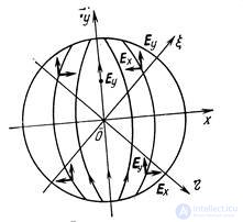
Phenomena distortion of the resulting radar DNA when irradiated with a field with orthogonal polarization is used when creating interference on cross-polarization.
The structure of cross-polarization diagrams depends on many factors: the curvature of the reflector, the type of feed, the feed of the feed from the focus and diffraction at the edges of the mirror, nearby bodies, radome, etc. The level of this radiation is small. For mirror antennas it is - (10 - 20) dB relative to the main maximum.
A typical disturbance designed to suppress the receiver with AGC is a powerful intermittent disturbance. During the leading edge of the pulse, the control voltage does not have time to reach the magnitude that provides the linear gain mode, and the receiver is overloaded. In the pauses between the noise pulses, the sensitivity of the receiver may not be able to recover to the required value, which ensures the reception of a weak (compared to the noise) signal.
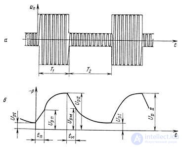
Here is a general case when during T1 of the Up interference with amplitude Uin1, the receiver overloaded for the time tp has time to get out of the overloaded state before the end of the pulse interference. During T2 of the signal with amplitude Uin 2, the AGC system is first open (dead time tm), then until the next interfering pulse arrives, the AGC system is closed.
Up = Up1 - voltage at the time of receipt of the next interfering pulse;
Up = UpII - voltage at the time of the end of the interfering pulse;
Up = Upn - voltage at the points of exit from overload mode;
Up = Upm - voltage at the end of the "dead" time, where sensitivity is restored.
The higher the speed of the AGC system, the shorter the time tп during which the receiver is overloaded.
With a very small period of interference (compared to the time constant of the AGC filter), there is practically no overload. On the contrary, for a low frequency of interference, an overload always takes place, since during the half-period T2 the filter capacitor has time to discharge and each new interference pulse catches the receiver at high sensitivity.
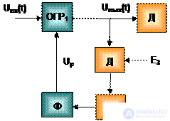
When the receiver is overloaded, the voltage amplitude at its output remains unchanged, equal to a certain threshold value Uthr, regardless of how the signal at the input subsequently changes. The exit from saturation occurs when the amplitude of the voltage at the output due to the increase in the regulation voltage and a decrease in the gain factor drops to a value smaller than E s .
Thus, between Uвх1 and Uвх2 there is a dependence  .
.
If Uin2 rises above the level Uin1 (Ez / Uthr), then in half-periods T2, the signal at the receiver output has time to rise above the level Ez.
These arguments show that with fixed AGC parameters you can always choose interference parameters so that there will be loss of information concluded in changing the signal amplitude due to temporary overload after exposure to the next interference pulse and due to temporary loss of sensitivity after the end of the interference pulse.
As the main object of radio suppression, there are military radio communication systems.
Radio communication systems (CCF) are understood to mean the organizational and technical unification of communication forces and means created in the appropriate military structures to control troops (forces) and weapons in an operation (combat) and in their daily activities.
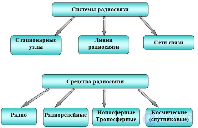
Under the radio line understand the set of technical devices and the environment of propagation of radio signals, ensuring the formation of one or more radio channels (RS).
Cattle is an elementary object of radio-suppression of VRS.
A radio communication channel as an element of radio suppression of an ASS is a set of transmitting and receiving technical devices and a propagation medium intended for carrying out radio communication (information transfer) at a working (assigned, assigned) radio frequency (set of operating frequencies).
Generalized block diagram of bilateral LSR 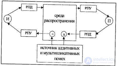

 ,
, 
 ,
,  ,
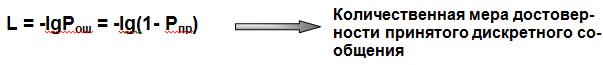
, where Rosh (q <q 0 ) is the probability of the total error as a function of the signal-to-noise ratio q = PS / Pn with optimal reception methods; q0 is the threshold signal-to-noise ratio corresponding to the required reliability of information transfer  .
.
Signal / noise threshold ratio
Type of | Radio telegraphy | Low speed | Two-dimensional ensembles | ||||||||
FM | World Cup | AM | World Cup -AM | Q = 1024 | Q = 256 | Q = 2 | FM | KAM | |||
Q = 16 | Q = 4 | Q = 8 | Q = 16 | ||||||||
Rosh = 10-7 | 28 | 52 | 110 | - | "thirty | "80 | 15 | - | 14 | nineteen | 22 |
Rosh = 10-5 | 20 | 38 | 50 | 110 | "50 | "56 | eleven | 25 | eleven | 17 | 21 |
Rosh = 10-3 | ten | 20 | 40 | 70 | "thirty | "32 | ten | 21 | ten | sixteen | 17 |
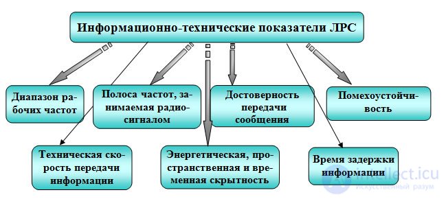
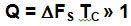
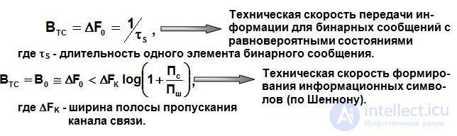
Для бинарных сообщений с равновероятными состояниями техническая скорость передачи информации Втс численно равна ширине полосы спектра DF0, в пределах которой находится значительная часть энергии сигнала.
Для передачи телеграфных сигналов и данных со скоростью до 1200 ... 2400 бит/с в СРС используются узкополосные КС, в том числе со специальной аппаратурой уплотнения. Высокоскоростная (более 2,4 х 103 бит/с) передача данных осуществляется по широкополосным каналам. В тропосферных СРС — до 2 Мбит/с.
Радиорелейные линии (РРЛ) связи по пропускной способности, можно разделить: на РРЛ
с малой пропускной способностью — В0 < 10 Мбит/с;
со средней — 10 Мбит/с < В0 < 100 Мбит/с;
с большой — В0> 100 Мбит/с.
 , которой, соответствует пороговое отношение сигнал/шум и нижняя граница пропускной способности КС.
  , определяет пороговое отношение сигнал/шум
  , и является необходимым условием, для определения информационного ущерба наносимого средствами РПД.
 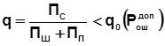 .
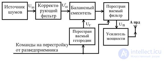
. Основными средствами радиоподавления СРС являются автоматизированные станции помех (АСП) и комплексы радиоэлектронного подавления (КРП).
АСП - техническое устройство, которое включает передатчик помеховых сигналов и совокупность подсистем, осуществляющих обнаружение и измерение параметров сигналов, их анализ, а также контроль за эффективностью подавления, и предназначено для исключения или затруднения (нарушения) функционирования СРС как целей радиоподавления.
КРП - совокупность АСП и (или) передатчиков помех, устройств (средств) радиоразведки (обнаружения, распознавания, пеленгации и т.д.) и пунктов управления, функционально связанных и совместно применяемых по единому алгоритму для решения задач радиоподавления СРС и (или) информационных датчиков СУ.
Типовая структурная схема КРП
с одним уровнем управления 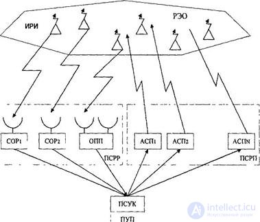
Тактико-технические характеристики КРП (АСП):
Таблица - Типовые значения технических характеристик АСП
 Тип АСП Параметр Тип АСП Параметр | Р-378А | Р-325П5 (передатчик) | Р-ЗЗ0Б | Р-377А (передатчик) |
| Диапазон (МГц) | 1,5 ... 30 | 1,5 ... 30 | 30... 100 | 20 ... 400 |
| Вид управления | ручной auto централизобанный | дистанционное | ручной auto централизовэнный | дистанционное |
| Время на подавление, с | 0,8 ... 1,5 | - | 0,8 ... 1,5 | - |
| Время на контроль, с | 0.2 | 0.2 | ||
| Время на доразведку, с | 0.5 | 0.3 | - | |
| Максимальное время перестройки, с | 0.3 | 0.3 | 0.3 | - |
| Выходная мощность, Вт | 103 | 5 х 103 | 103 | 3±1,5 |
| В иды помех | ХИП ЧТ шумовая ЧМ | - | ХИП ЧТ шумовая ЧМ | шумовая |
| Вид антенны | l - образная логопериодическая | логопериодическая | штыревая дискоконусная | |
| Sensitivity разведприемника: в ручном режиме, мкВ в автоматическом режиме, мкВ/м | 1.5 15 | - | 1,6 7 | - |
 (1.28)
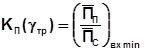
  и помеховой
  составляющей в динамике конфликта при оценке надежности эффективности радиоподавления ЛРС требуется учесть не только свойства ЛРС и качество (структуру и энергетические параметры) помехи, которые определяются коэффициентом подавления (1.28), но и динамические особенности поведения противостоящих сторон (ЛРС и АСП, СРС и КРП) с учетом априорной информации о состоянии каждой из них.
 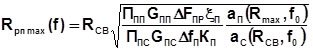 (1.29)
  , (1.30)
 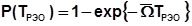 , (1.31)
 Where 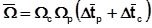 - average frequency of coincidence of flows;
  - average frequency and duration of activation of LRS on radiation;
  - the average frequency and duration of stay of the LSR emissions in the antenna pattern of the radio intelligence stations of the SRR PKR.
From the relation (1.31) it is easy to obtain an estimate of the time of opening the electrical equipment: 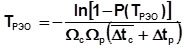 .
.
 , (1.33)
  (1.34)
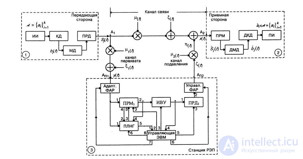

Comments
To leave a comment
Devices for the reception and processing of radio signals, Transmission, reception and processing of signals
Terms: Devices for the reception and processing of radio signals, Transmission, reception and processing of signals