Lecture
Despite all the measures listed in the previous chapter for increasing the stability of the local oscillators, it is difficult to obtain the relative frequency stability above the value of 10-3 ... 10-4. This instability leads to a departure of the tuning frequency of the radio receiver at a frequency of 100 MHz at 100 ... 10 kHz. This value exceeds the width of the frequency channel of modern mobile communication systems. At higher frequencies, the position with absolute frequency drift depending on temperature is further deteriorated.
Therefore, work was done to increase the stability of frequency-generating elements. As a result, it was possible to obtain stability by two orders of magnitude when quartz resonators were used as frequency-generating elements. In this case, it is possible to ensure the relative stability of the frequency of the generator from 10–5 to 10–8.
Quartz resonator is used in the local oscillators of radio receivers as a frequency-determining oscillatory resonant LC circuit. Due to the small energy losses in this cavity, it is possible to achieve a good quality of the order of several thousand.
Consider how the quartz resonators, and on what principles they work. Quartz crystals are known in nature as rock crystal, amethyst or rauchtopaz. As an example, Figure 1 shows a photograph of druses of rauchtopaz crystals.
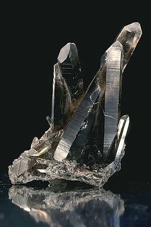
Figure 1. Appearance of quartz crystals
Natural quartz crystals are mined mainly in the mines of Brazil. Natural quartz crystals contain a large number of inhomogeneities. In addition, they are expensive, so at present, artificially grown quartz crystals are mainly used. Quartz crystals are grown from alkaline solutions in autoclaves at a temperature of 400 ° C and a pressure of about 2000 atm. The process of growing a crystal lasts from 30 to 45 days.
A feature of quartz crystal is that it has a piezoelectric effect. The piezoelectric effect is caused by the special structure of a quartz crystal. It is a regular hexagonal prism. Schematically, the arrangement of oxygen and silicon ions in a quartz crystal is shown in Figure 2.
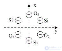
Figure 2. The location of ions of oxygen and silicon in a quartz crystal
The electric axis x and the mechanical axis y are clearly observed in the crystal. When a crystal is compressed along the mechanical axis y, negative oxygen ions are displaced on one side, and positive silicon ions on the other. The result is a potential difference. Compression or stretching along the Z axis does not cause the appearance of charges on the faces. Therefore, the Z axis is called optical.
Due to the symmetry of a quartz crystal, the mechanical and electrical axes can be carried out in three different ways. The effect will not change. Figure 3 shows how to cut a plate from a quartz crystal so that a potential difference occurs at its edges.
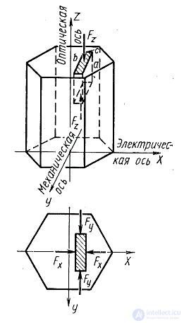
Figure 3. How a piezoelectric quartz crystal plate is cut.
The slice shown in Figure 3 is called the XT slice. The change in the XT dimensions of the slice of a quartz plate when a potential difference is applied to its surface is shown in Figure 4.

Figure 4. Resizing an XT cut of a quartz plate when a potential difference is applied to its surface
XT-cut used for the manufacture of low-frequency quartz resonators. For example, clock resonators at a frequency of 32768 kHz. A drawing of a watch quartz resonator is shown in Figure 5. It is designed as a tuning fork plug. This form, as in the musical technique, allows to obtain a very high Q-factor of the resonator.
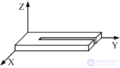
Figure 5. Drawing of the fork of the watch quartz resonator
The oscillation shape of the tuning fork shoulders of the watch quartz resonator is shown in Figure 6.
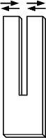
Figure 6. The oscillations of the arms of a watch quartz resonator
A photograph of a watch quartz resonator with the protective case removed is shown in Figure 7.
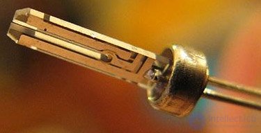
Figure 7. The appearance of a watch quartz resonator
It should be noted that a similar cut of the quartz plate does not allow to obtain a high stability of the oscillation frequency. Figure 8 shows the typical dependence of the frequency deviation of a quartz resonator XT-cutoff on the ambient temperature.
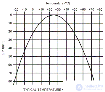
Figure 8. Dependence of the departure of the resonant frequency on the temperature for the XT cut of a quartz plate
As can be seen from this graph, when the temperature changes from –25 ° C to + 75 ° C, the frequency goes to 80 millionths (ppm). This corresponds to a frequency stability of 10–4, which is quite enough for the operation of a wristwatch, microprocessor synchronization, but too little to stabilize the carrier frequency of transceivers.
The AT cut of a quartz crystal has much better characteristics. Unlike the XT cut, in the AT cut, the plate is cut at an angle to the mechanical axis Z. Its value is 35 ° 15 '(at frequencies above 10 MHz, the cut angle will be 35 ° 18'). Therefore, a shift in thickness is formed in the plate when applying an alternating voltage, as shown in Figure 9.
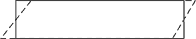
Figure 9. Shift of the AT-cut surfaces of a quartz plate when a potential difference is applied to them
In an AT resonator, its resonant frequency depends on the thickness of the plate. The thickness of the quartz plate is defined as 1.661 mm / (frequency in MHz). The plate can be cut into strips and placed in the same case as the quartz watch.
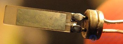
Figure 10. The appearance of a compact quartz resonator with AT-cut
However, to reduce losses and eliminate parasitic oscillations at unwanted frequencies (and this is what is required in the local oscillators of radio receivers and transmitter pathogens), the shape of the plate is made in the form of a disk or lens. An external view of a quartz resonator with an AT-cut plate is shown in Figure 11.
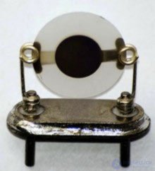
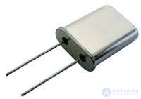
Figure 11. The appearance of the quartz resonator with AT-cut
Figure 12 shows typical dependences of the frequency deviation of an AT-cut quartz resonator on the ambient temperature for various deviations of the cut-off angle from the optimal value of 35 ° 15 '.
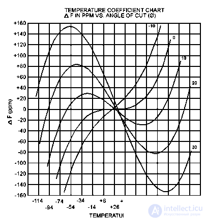
Figure 12. Typical temperature dependences of the frequency drop of a quartz resonator AT-cutoff
As can be seen from the graph, with exact observance of the cut-off angle of a quartz crystal, in the same temperature range, the frequency deviation of the quartz resonator does not exceed ± 10 ppm. This corresponds to frequency instability 10–5.
The equivalent circuit of the quartz resonator is shown in Fig. 13, and the characteristic of its resistance versus frequency is shown in Fig. 14.
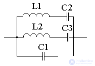
Figure 13 - equivalent circuit of a quartz resonator
Sequential contours in this equivalent circuit display the main oscillation frequency of the plate, the third and, if necessary, the fifth harmonic of the main oscillation. Capacitor C1 displays the capacity of the quarter holder.
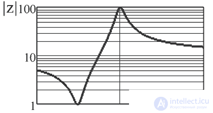
Figure 14 - Dependence of the resistance of the quartz resonator on the frequency
In the frequency range from series resonance (minimum of resistance) to parallel resonance (maximum of resistance) the quartz resonator possesses inductive resistance. One of the most common schemes of quartz oscillators, made on a bipolar transistor, is shown in Figure 15.
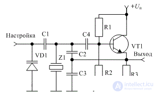
Figure 15 - Diagram of a crystal oscillator on a bipolar transistor
This is a typical Kolpitz scheme in which a Z1 crystal is used instead of an inductor.

Comments
To leave a comment
Devices for the reception and processing of radio signals, Transmission, reception and processing of signals
Terms: Devices for the reception and processing of radio signals, Transmission, reception and processing of signals