Lecture
In a diode converter, two signals are simultaneously applied to the input of a nonlinear element, which is a diode, that is, the input received signal voltage and the local oscillator voltage. In the general case, a bias voltage E0 can be applied to the same diode, which will provide the necessary level of cut-off of the local oscillator signal. One of the variants of the circuit diagram of a diode signal mixer with the possibility of setting the bias current through a mixing diode is shown in Figure 1.
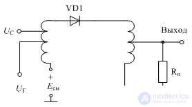
Figure 1. Diode Mixer Diagram
In case of a short circuit at the output of the circuit, the current through the diode will be completely determined by its static current-voltage characteristic:

Volt-ampere characteristic of frequency-transforming diodes is approximated by the function
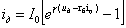
where I 0 is the saturation current of the reverse biased pn junction of the diode;
rb is the diode base resistance;
g - coefficient equal in most diodes to 20-40 V – 1
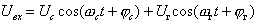
The voltage at the input of the diode converter is determined by the sum of the input signal, the local oscillator signal and the bias voltage.
The voltage at the input of the diode converter, the current-voltage characteristic of the diode, and the current at its output are shown in Figure 2.
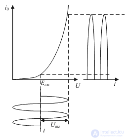
Figure 2. The shape of the voltage and current of the local oscillator in a diode frequency converter
As can be seen from this figure, the output current will mainly depend on the voltage of the local oscillator, so the component of this signal will naturally be present in the output signal spectrum. In addition, the current in the circuit also depends on the desired signal, which means that this component will also be present in the output signal spectrum. You can get rid of the extra spectrum components in the output signal only with a band-pass filter. Current output spectrum of the diode converter and filter characteristic
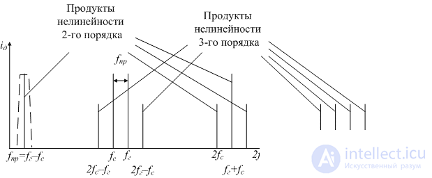
Figure 3. Diode mixer output spectrum
As can be seen from Figure 2, the shape of the current, and, consequently, the voltage at the output of the converter does not match. This means that harmonic signal harmonics are generated at the output of the converter. The harmonic signal level of the local oscillator significantly depends on the cut-off angle of the sinusoidal oscillation, which in turn depends on the bias voltage Ecm and on the amplitude of the heterodyne voltage Umg.
In [1], it was shown that there exist signal levels of the local oscillator, at which there are no nonlinearity products of the second and third order. The conversion ratio of the diode mixer can not exceed the values  . Graph of dependence of the conversion factor of the diode mixer on the level of the local oscillator signal and the resistance of the signal source and load is shown in Figure 4
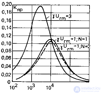
Figure 4. Diode mixer conversion factor
The parameter R on this graph corresponds to the series connection of the impedance of the radio source and the load of the diode mixer. From Figure 5.5 it can be determined that
1. The conversion factor of the diode mixer increases with increasing amplitude of the local oscillator signal. The resistance of the signal source and the load should be reduced.
2. An increase in the bias current of the mixer diode leads to a decrease in the required resistances of the signal source and load. The transmission coefficient of the mixer remains constant.
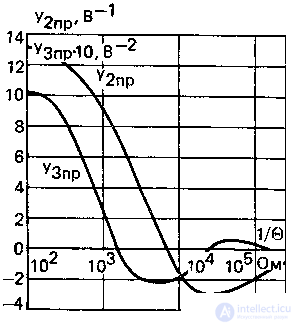
Figure 5. Conversion factor of the diode mixer on the second and third harmonics of the local oscillator.
It should be noted that the oscillation mode of the local oscillator has a significant impact on the nonlinear distortion of the mixer. In [2], it was shown that when it approaches a rectangular, nonlinear distortions of the diode mixer decrease significantly.

Comments
To leave a comment
Devices for the reception and processing of radio signals, Transmission, reception and processing of signals
Terms: Devices for the reception and processing of radio signals, Transmission, reception and processing of signals