Lecture
The task of selecting the law of frequency change from the received signal is very common. This task is encountered both when receiving signals with analog frequency modulation methods and when receiving signals with digital modulation methods, such as FFSK or GMSK. We do not even think about listening to FM radio stations in the car or in the outdoors, that in a portable or car radio, sound is emitted from a radio signal using a frequency detector. Dialing a number on a cell phone, we also use this device. Therefore, at present, any specialist who is looking for a job in a specialty related to radio should represent the principles of operation of a frequency demodulator.
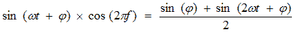
This article will not consider such museum rarities as a relationship detector or a fractional detector. Now frequency detectors are based on analog frequency multipliers. A signal with frequency modulation of a sinusoidal low-frequency modulating signal is described by the following mathematical expression:

Before turning to specific frequency detector circuits, we turn to the mathematical definition of the concept of frequency:

From this formula it is clear that the frequency and phase of the input oscillation are rigidly connected with each other by the operation of differentiation (integration). To detect frequency-modulated oscillations, you can apply a phase detector circuit, and then differentiate the output voltage on a differentiating RC-chain.
The block diagram of the frequency-phase detector, implemented according to the principle described above, is shown in Figure 1.
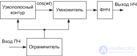
Figure 1. Block diagram of the frequency-phase detector
In this scheme, the narrowband circuit converts the frequency-modulated oscillation into a phase-modulated oscillation due to the phase-frequency response of the narrow-band circuit. Using the concept of an analog signal multiplier considered earlier, we obtain a circuit diagram of a frequency detector.
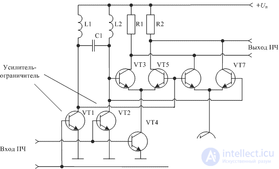
Figure 2. Schematic diagram of the frequency-phase detector
Such schemes of phase detectors are widely used in technical solutions of radio receivers. As an example, Figure 3 shows a diagram of a frequency-phase detector, implemented on a domestic 174UR3 chip.
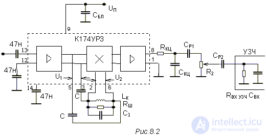
Figure 3. Frequency-phase detector on a 174UR3 chip
Currently, most single-chip FM receivers work on this principle. As an example, you can call the chips K174HA26, MC3361, MC3371, SA616. The same microcircuits can also be used as part of higher-quality hardware provided that the first amplifier stages of the receiver are implemented on a higher-quality element base. An example of the use of chip SA616 as a path of the second intermediate frequency radio station was considered by us in the article UPCH FM
In some cases, phase-locked loop is used for frequency detection. It allows, at low cost, to obtain high quality parameters of the frequency detector as a whole. The block diagram of such a detector is shown in Figure 4.
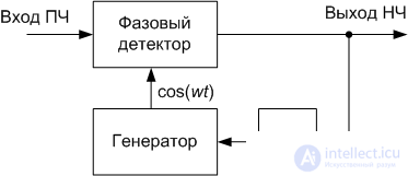
Figure 4. Block diagram of the frequency detector implemented on the PLL
In this scheme, the generator is adjusted to the frequency of the input signal. At the output of the phase detector produces an error signal frequency control. This signal is proportional to the frequency deviation of the input frequency-modulated signal. The low pass filter determines the capture bandwidth of the PLL.

Comments
To leave a comment
Devices for the reception and processing of radio signals, Transmission, reception and processing of signals
Terms: Devices for the reception and processing of radio signals, Transmission, reception and processing of signals