Lecture
When designing a base station or repeater, you should consider the fact that the antenna is significantly removed from the input of the radio receiver. To connect the antenna with a radio receiver, you have to use an antenna feeder that has losses. An example of the relative position of the antenna and receiving and transmitting equipment of the base station is shown in Figure 1.
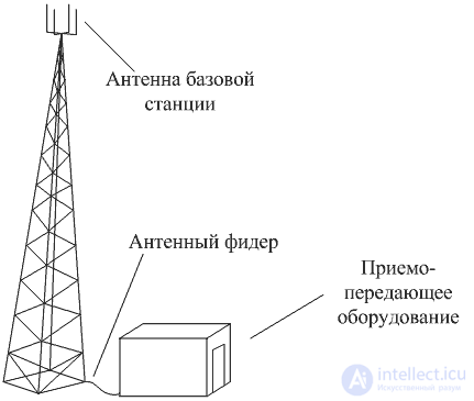
Figure 1 Mutual arrangement of the antenna and transceiver equipment of the base station
Of course, the loss of the antenna feeder could be compensated by an amplifier located directly at its input, however, a number of difficulties arise. The first is how to supply power to this unit? The second is how to maintain and repair this unit. These difficulties increase significantly in winter. Therefore, it is more cost-effective to compensate for feeder losses with antenna gain.
When designing radio receiving devices of base stations in mobile communication systems, there is a requirement to distribute the signal energy from the output of a receiving or receiving and transmitting antenna to the inputs of several radio receivers. The problem is that when dividing the power of a radio signal, the signal-to-noise ratio at the output of radio receivers deteriorates, so usually the power is divided in several stages.
The transfer ratio of the power distributor to the two outputs cannot be better than –3 dB. Therefore, at its input a low-noise amplifier is usually placed, as shown in Figure 2.
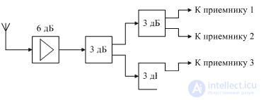
Figure 2. Block diagram of the input signal divider
In the above scheme, a low-noise amplifier increases the input signal level by 6 dB. Then the output signal of this amplifier is divided between four inputs of radio receivers. Naturally, all channels of radio receivers must be in the passband of this low-noise amplifier.
Power dividers are usually performed on transformers or on microstrip lines, but even if a transformer is used in the power divider, it is wound by conductors with a strictly defined characteristic impedance. An example of a signal power divider into four single-ended outputs is shown in Figure 3.
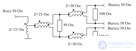
Figure 3 Diagram of a power divider into four single-ended outputs.
This diagram shows the wave resistance of microstrip lines for the case of input and output impedances equal to 50 Ohms. The use of windings in the form of a transmission line with a specific characteristic impedance is of fundamental importance. The issues of calculating power dividers are discussed in detail in [1].
Currently, the input power dividers are produced by a number of companies in the form of ready-made modules. Examples include firms such as Ikusi, RTM, Rexant. An example of the appearance of the finished splitter modules is shown in Figure 4.
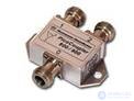
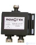
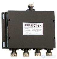
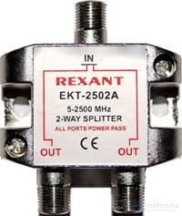
Figure 4 The appearance of the modules of the input power splitters (splitters)

Comments
To leave a comment
Devices for the reception and processing of radio signals, Transmission, reception and processing of signals
Terms: Devices for the reception and processing of radio signals, Transmission, reception and processing of signals