Lecture
Mixers on transistors provide great opportunities for the construction of schematic diagrams in comparison with diode frequency converters. However, the best performance, as in the case of diode mixers, have ring frequency converters. Since the circuit of the ring converter is obtained by connecting two balanced frequency converters, we first consider the schematic diagram of a transistor balanced mixer. Its diagram is shown in Figure 1.
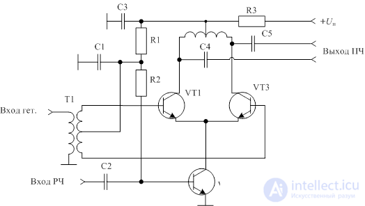
Figure 1. Diagram of a transistor balanced mixer
In the circuit shown in Fig. 1, the frequency currents of the received signal flowing through transistors VT1 and VT3 create a common-mode voltage at the output that is compensated at the input of the next stage (or the input of a band-pass filter of intermediate frequency). The signal of the local oscillator in this circuit freely passes to the output of the converter, but is compensated for at the collector of the transistor VT2, therefore, is significantly attenuated at the input of the radio frequency of this converter.
To suppress the signal of the local oscillator at the output of the frequency converter, a second balanced mixer is used. If at its inputs the local oscillator signal is fed in antiphase with respect to the first balanced mixer, then when the outputs of balanced mixers are connected in parallel, the local oscillator signal in the output spectrum of the converter will be suppressed. As a result, a dual balanced transistor frequency converter circuit will work like a signal multiplier. Diagram of the transistor ring mixer is shown in Figure 2.
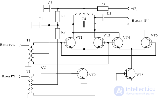
Figure 2. Diagram of the transistor ring mixer
In this scheme, the first balanced mixer is assembled on transistors VT1 ... VT3, the second balanced mixer is assembled on transistors VT4 ... VT6. In order for the intermediate frequency current to be summed across the load, the voltage at the radio frequency inputs of balanced transducers is supplied in antiphase.
However, the difference between the current-voltage characteristics of the transistors and the quadratic law leads to non-linear distortions of the received signal, therefore, in some cases, the transistors in the ring mixer are used in the key operation mode. With this mode of operation of the transistor, it is either in the closed state or in the open. In any of these modes, the transistor can be considered ohmic resistance.
The fact that in the key operation mode of the transistor, the signal of the local oscillator becomes rectangular, must be taken into account when choosing the frequencies of the local oscillators and the frequency band of the signal entering the input of such a frequency converter. The circuit of the ring transistor mixer operating in the key mode is shown in Figure 3.
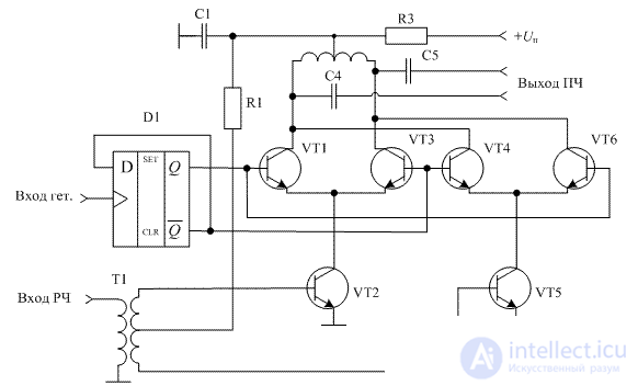
Figure 3. Diagram of a ring mixer operating in key mode
Since the oscillation of the local oscillator is formed by a digital circuit, it is possible to obtain a voltage with only two levels. As already discussed above, this form of heterodyne voltage allows for the implementation of highly linear frequency converters.
In the ring mixer circuit, it is important that the duty cycle of the local oscillator signal is 2, so the counting flip-flop D1 is included in the chip, providing a square wave at its output with very high accuracy. At the same time, this trigger lowers the local oscillator signal frequency by half. This circumstance should be considered when designing a radio receiver.
Since this scheme is standard, by now a sufficiently large range of integrated circuits of mixers operating according to this principle is being produced. The use of integrated technology allows to ensure the identity of the parameters of the transistors of the ring mixer and thereby the suppression of the signals of the local oscillator and the signal in the output circuit. The task of the developer of the radio receiver in most cases is reduced to the choice of a chip with the given parameters. An example of such a mixer is the AD8344 chip.

Comments
To leave a comment
Devices for the reception and processing of radio signals, Transmission, reception and processing of signals
Terms: Devices for the reception and processing of radio signals, Transmission, reception and processing of signals