Lecture
Under the radio transmitting device (RPDU) understand the complex of equipment intended for the formation and emission of radio signals. The main nodes of the PDU are the carrier frequency generator and the modulator. In modern communication systems, the RPDU also contains other equipment that ensures the joint operation of communication facilities: power sources, synchronization systems, automatic control, monitoring and alarm systems, protection, etc.
A generalized block diagram of a radio transmitting device with amplitude or phase modulation of signals is shown in Figure 7.9.
The primary signal to be transmitted enters the input circuit. The input circuit ensures that this signal is matched to the DUT, ultimately, this is determined by the parameters of the modulated radio signal transmitted to the line.
The carrier frequency generator generates *** carrier frequency, which are carriers of the message. In modern communication systems, the carrier frequency generator is performed as a frequency synthesizer. Frequency synthesizer is a device designed to form in a given frequency range highly stable coli ***, determined by the stability of the parameters of the master oscillator.
A modulator is a node in which a transmitted message is superimposed on the parameters of the carrier. When radio signals with amplitude or phase modulation are formed in the RFCU, the frequency synthesizer produces colorations of *** with a constant frequency. With an additional effect of the modulating signal on the frequency of the output frequency *** of the frequency synthesizer, you can receive radio signals with frequency modulation.
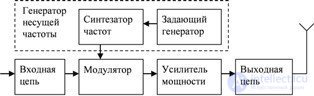
Fig. 7.9 Generalized block diagram of a radio transmitting device
The advantages of digital information processing methods (transmission, storage, transformation) have contributed to the wide distribution of digital communication systems. The advantage of presenting signals in digital form is also its versatility, that is, independence from the nature of the transmitted messages. Modern communication systems are capable of transmitting not only discrete messages, but also continuous ones (both in time and in level). To convert continuous signals into digital are special devices - analog-to-digital converters (ADC).
In the analog-digital converter, from a signal that is continuous in time, first select the signal values at certain points in time. Most often, such counts are taken at regular intervals. The selected values of the signal are called samples, and the operation of obtaining samples is called time discretization.
At the next stage of processing, the entire range of possible signal values is divided into a certain number of intervals and find out which of these intervals the current sample value belongs to. At this stage of processing, the signal value is not the actual value of the sample, but the nearest rounded value of the signal. This value can correspond to the middle of the interval in which the given reading falls, or to another value from this interval (the beginning or the end of this interval). The operation of replacing the actual value of the signal with the nearest rounded value is called quantization, and the width of this interval is called the quantization step. If all the intervals into which the possible signal values are divided are the same, then such quantization is called uniform. In some cases, for example, when transmitting speech, it turns out to be beneficial to make such intervals unequal. In this case, talking about non-uniform quantization.
At the last stage, the analog-to-digital converter replaces the actual sampling value with the number of the interval within which the value of this reference is located. The operation of replacing the value of the reference number (code) is called coding. The most widespread in modern systems received the presentation of samples in the form of binary codes. Then the received codes are transmitted via the communication system.
A simplified block diagram of a transceiver digital communication system is shown in Figure 7.10. Consider the operation of this device.
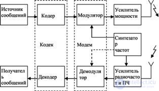
Fig. 7.10 Digital Transceiver Transceiver
A continuous message from the message source is sent to a device called an encoder. Under the coding in a broad sense, understand the operation of converting samples of continuous signals into a sequence of code symbols. As a result, electrical signals are generated at the output of the encoder, corresponding to the code sequence and determined by the transmitted message.
The code signals in the form of a sequence of pulses are then fed to a modulator, to the second input of which a carrier frequency is fed from the output of the frequency synthesizer. The modulator performs the corresponding modulation (amplitude, phase, frequency, etc.) of the carrier frequency in *** according to the incoming code sequence. The modulated signals are then amplified to the required level with a power amplifier and radiated by the transmitting antenna.
Electromagnetic radiation induced in the receiving antenna is fed to the input of the amplifier and the frequency converter, where the useful *** carrier frequency is distinguished and amplified. A demodulation of the received message is performed in the demodulator, and a sequence of pulses is formed at the output of the demodulator, corresponding to the sequence of pulses of the message being transmitted (at the encoder output), which is fed to the decoder. The decoder performs the operation opposite to the encoding, and the recovered message is sent to the recipient of the messages.
In one transceiver device, the encoder and decoder are usually combined into a single constructive node (more often, it is one chip) and the combined codec block is called a codec by the first letters of the components. Similarly, the combined modulator-demodulator unit is called a modem.
Radio transmitting devices differ in purpose, operating conditions, type of modulation of radio signals and other characteristics.
The main energy indicators RPDU include the amount of signal power supplied to the antenna, and efficiency. A distinction is made between the peak power of the wanted signal and the average power over a certain time interval. The coefficient of performance is the ratio of the net power supplied to the antenna to the power consumed *** by the RPDU from the power source.
The frequency range in which this RPNU operates is understood to be such a frequency band that is necessary for transmitting useful signals in the communication system and is allocated to this RPD for generating radio signals. Unfortunately, in addition to the useful signals, the radio transmitting devices also emit side-rings.
Out-of-band emissions are called such signals, formed by the RPDU, whose spectra are located outside the band allocated for this communication system. Out-of-band emissions are sources of additional interference for communication systems operating in other frequency bands.
An important characteristic of communication systems is the stability of the frequency of emitted rings *** ***. Under the instability of the frequency RPDU understand the frequency deviation of the emitted col *** *** relative to the nominal value. Insufficient frequency stability degrades the quality of communication and can cause interference to radio devices operating in adjacent frequency bands.
By appointment, radio transmitters are divided into communications and broadcasting. According to the operating conditions of the DAP, they are divided into stationary and mobile (installed on mobile objects: aircraft, automobile, wearable, etc.). RPDU also differ in the operating frequency range, the power of the radiated col ***, etc.

Comments
To leave a comment
Devices for the reception and processing of radio signals, Transmission, reception and processing of signals
Terms: Devices for the reception and processing of radio signals, Transmission, reception and processing of signals