Lecture
Under the transition (dynamic, non-stationary) process or mode in electrical circuits refers to the process of transition of the circuit from one steady state (mode) to another. Under steady-state, or stationary, modes in DC circuits, voltages and currents are constant over time, and in AC circuits they are periodic functions of time. Steady-state modes with specified and unchanged circuit parameters are fully determined only by the source of energy. Consequently, sources of constant voltage (or current) create a constant current in the circuit, and sources of alternating voltage (or current) - alternating current of the same frequency as the frequency of the energy source.
Transition processes - processes that occur in electrical circuits under various influences that lead to a change in their mode of operation, that is, under the action of various switching equipment, for example, keys, switches to turn on or off a source or receiver of energy, with breaks in the circuit, with short short circuits of individual sections of the circuit, etc.
The physical cause of transient processes in the circuits is the presence of inductors and capacitors in them, that is, inductive and capacitive elements in the corresponding equivalent circuits. This is explained by the fact that the energy of the magnetic and electric fields of these elements cannot change abruptly when switching (the process of closing or opening the switches) in the circuit.
The transition process in the circuit is described by a differential equation
Transients occur when any changes in the electrical circuit mode: when connecting and disconnecting the circuit, when the load changes, when emergency modes occur (short circuit, wire break, etc.). Changes in the electrical circuit can be represented in the form of certain switchings, generally referred to as switching. Physically, transient processes are processes of transition from an energy state corresponding to the switching mode to an energy state corresponding to the following switching mode.
Transients are usually fast flowing: their duration is tenths, hundredths, and sometimes billionths of a second. Relatively rarely, the duration of transients reaches seconds and tens. Nevertheless, the study of transients is very important, because it allows you to establish how the signal is deformed in form and amplitude, to identify voltage surges on certain sections of the circuit that may be dangerous for the insulation of the installation, increasing the amplitudes of the currents that can exceed the current amplitude tenfold. established periodic process, as well as determine the duration of the transition process. On the other hand, the work of many electrical devices, especially industrial electronics devices, is based on transients. For example, in electric heating furnaces, the quality of the material produced depends on the nature of the flow of the transient process. Excessively fast heating can cause a defect, and excessively slow negatively affects the quality of the material and leads to a decrease in performance.
In the general case, transients may occur in an electrical circuit if there are inductive and capacitive elements in the circuit that have the ability to accumulate or release energy from a magnetic or electric field. At the moment of switching, when the transition process begins, there is a redistribution of energy between the inductive, capacitive elements of the circuit and external energy sources connected to the circuit. In this case, part of the energy is irrevocably converted into other types of energy (for example, into thermal energy with active resistance).
After the end of the transition process, a new steady state is established, which is determined only by external energy sources. When external energy sources are disconnected, the transient process may occur due to the energy of the electromagnetic field accumulated prior to the beginning of the transient mode in inductive and capacitive elements of the circuit.
Changes in the energy of the magnetic and electric fields cannot occur instantaneously, and, therefore, processes cannot instantaneously flow at the moment of switching. In fact, an abrupt (instantaneous) change in energy in an inductive and capacitive element leads to the need to have infinitely large powers p = dW / dt, which is practically impossible, because in real electrical circuits an infinitely large power does not exist.
Thus, transients cannot flow instantly, since it is impossible in principle to instantly change the energy accumulated in the electromagnetic field of a circuit. Theoretically, transients end in time t → ∞. In practice, transients are fast-flowing, and their duration is usually a fraction of a second. Since the energy of the magnetic W M and electric fields W E described by the expressions

 ,
,
then the current in the inductance and the voltage on the capacitance cannot change instantly. The switching laws are based on this.
The first law of switching is that the current in the branch with the inductive element at the initial moment of time after switching has the same value that it had just before switching, and then from this value it begins to change smoothly. This is usually written in the form i L (0 - ) = i L (0 + ), considering that the switching occurs instantaneously at the moment t = 0.
The second law of switching is that the voltage on the capacitive element at the initial moment after switching has the same value as it had just before switching, and then from this value it begins to change smoothly: U C (0 - ) = U C (0 + ).
Consequently, the presence of a branch containing an inductance in the voltage circuit is equivalent to breaking the circuit at this point at the moment of switching, since i L (0 - ) = i L (0 + ). The presence in the voltage circuit of a branch containing a discharged capacitor is equivalent to a short circuit in this place at the moment of switching, since U C (0 - ) = U C (0 + ).
However, in the electric circuit voltage surges on inductances and currents on capacitors are possible.
In electrical circuits with resistive elements, the energy of the electromagnetic field is not stored, as a result of which transients do not occur in them, i.e. in such circuits, stationary modes are set instantly, abruptly.
In fact, any element of the circuit has some resistance r, inductance L and capacitance C, i.e. in real electrical devices there are heat losses due to the passage of current and the presence of resistance r, as well as magnetic and electric fields.
Transients in real electrical devices can be accelerated or slowed down by selecting the appropriate parameters of circuit elements, as well as through the use of special devices.
The task of studying transients is to find out by what law and for how long a noticeable deviation of the currents in the branches and voltages in the circuit sections from their steady-state values will be observed. So, for example, if in the studied branch of a certain circuit before switching there existed a direct current I 1 , and in steady state after switching it became I 2 , then we would be interested in the law of change of the transition current i between the switching moment (t = 0) and the unknown time point t 1 , when the transition process can be considered completed.
In the analysis of transients in electrical circuits, it is considered that:
The steady state before commutation is usually calculated on the assumption that by the time of commutation the previous transient process had ended in the circuit. Although sometimes it is necessary to analyze the transients that occur in the circuit, when the previous transition process caused by the previous switching has not yet ended. But this does not change the theoretical formulation of the problem.
The transient analysis is carried out by solving differential equations compiled for the electric circuit under study based on Kirchhoff's laws or the method of loop currents.
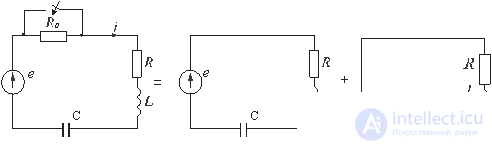
Fig. 5.1
Let the resistance suddenly change in a certain circuit (Fig. 5.1 a). Prior to switching, resistances R 0 and R existed in the circuit, only R remains after switching. It is required to determine the transient current i. The electrical state of the circuit after switching is described by an integro-differential equation written according to the second Kirchhoff's law for instantaneous values of currents and voltages:
(5.1)

If we differentiate this equation with respect to time, we obtain a second-order linear differential equation, in which the parameters of a circuit or their combinations act as constant coefficients:
(5.2)

It is known from mathematics that a complete solution of a linear differential equation with constant coefficients is found as the sum of a particular solution of an inhomogeneous and general solution of the corresponding homogeneous equation.
Since the right side of the differential equations describing the electrical state of the circuits is usually the voltage (or current) of the source (external driving force), a particular solution is found from the analysis of the steady state after switching. Hence, this mode is called forced and, accordingly, the currents or voltages found in this mode are called forced . Calculation of the forced mode, when external sources produce a constant or sinusoidal emf. (current), is not difficult and can be carried out by any known method.
The homogeneous differential equation is obtained from the expression (5.2) by “freeing” it from the right side. Physically, this means that the circuit under study is “released” from external driving force. The currents or voltages found in solving a homogeneous differential equation are called free . Free currents and voltages are the result of the action of internal sources of the circuit: emf. self-induction arising in coils, and voltages on capacitors, when both those and others are not balanced by external sources.
Schematically, the analysis of the transition process can be represented as the result of the imposition of two modes: coercive and free. The diagram in fig. 5.1 b should be calculated in the steady (forced) mode, and the diagram in fig. 5.1 v - in the mode when the circuit is released from external sources. Actual ( transient ) current in accordance with the principle of superposition is equal to the sum of steady (forced) and free currents:
i = i y + i of sv .
Note that physically there are only transient currents and voltages, and their decomposition into free and forced components is a mathematical technique that allows us to simplify the calculation of transients in linear circuits. Recall that the superposition principle applies only to linear chains.
There are various methods for solving a homogeneous differential equation obtained from expression (5.2):
(5.3)

The classic method of transient analysis is the direct integration of differential equations. The solution is found in the form of the sum of the exhibitors:
(5.4)
i CB = A 1 · e p 1 t + A 2 · e p 2 t ,
where the number of terms is equal to the order of the differential equation.
After substituting the exponentials of A k · e p k t into the original equation (5.3) and differentiation, we can obtain a characteristic equation from which the roots p 1 , p 2 are determined. If multiple roots are encountered (for example, p 1 = p 2 = P), the solution is A 1 · e Pt + A 2 · e Pt .
The integration constants A 1 , A 2 are found from the initial conditions, which are determined using the laws of commutation. There are independent and dependent (after switching) initial conditions. The first one includes the values of currents through inductances and the values of voltages on the capacitors, known from before the switching mode of the circuit.
The values of the remaining currents and voltages at t = 0 in after the switching circuit, determined by independent initial values from the Kirchhoff laws for the circuit after switching, are called dependent initial values.
The classical method of analysis is usually used to analyze processes in simple electrical circuits.
To analyze the transition process, one should first bring the scheme to the minimum number of energy storage devices, excluding parallel and sequential connections of reactive elements of the same type (inductances or capacitances). The system of integro-differential equations, compiled in accordance with Kirchhoff's laws or the method of loop currents, can be reduced by substitution to a single differential equation, which is used to compose the characteristic equation.
The order of the differential, therefore, the characteristic equation depends on the number of reactive elements of the above scheme. The main difficulty in solving the problem by the classical method for equations of higher order is in finding the roots of the characteristic equation and the integration constants. Therefore, other methods are used to solve equations of order higher than the second, in particular, an operator method based on the use of the Laplace transform and excluding the time-consuming procedure for finding the integration constants.
For practical purposes, when analyzing transients in any scheme using the classical method, the following algorithm can be recommended.
This section assumes not only practical familiarity with the classical method of calculating transients, but also with the peculiarities of the processes themselves in the problems under consideration.
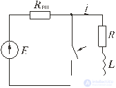
Fig. 5.2
We investigate electromagnetic processes in the circuit shown in fig. 5.2 occurring after the key closure.
We calculate the steady state in the circuit before commutation (before the key closes) and determine from it an independent initial condition - the current in the coil at the moment t = 0 - immediately preceding the commutation
i(0 - ) = i(0 + ) = E / (R вн + R).
Найдем установившийся ток i после коммутации. Так как во вновь образованном контуре из катушки L и резистора R нет источника, то i y = 0.
Для определения свободной составляющей тока запишем по второму закону Кирхгофа уравнение электрического состояния цепи после коммутации:
 .
.
Характеристическое уравнение имеет вид:
pL + R = 0.
Общее решение уравнения для свободной составляющей:
i св = A e pt ,
где: А – постоянная интегрирования;
p = - R/L, c -1 – корень характеристического уравнения.
Записав общий вид переходного тока катушки
i = i у + i св = A e pt ,
приравниваем его значение i(0 + ) = A в точке t = 0 + к значению i(0 - ), найденному в п. 1. Получаем искомую константу
A = E / (R вн + R) = I 0 .
Переходный ток i = i у + i св при этом равен
 ,
,
где τ = L / R – постоянная времени цепи.
Постоянная времени – это время, в течение которого свободная составляющая процесса уменьшается в е = 2,72 раза по сравнению с начальным значением.
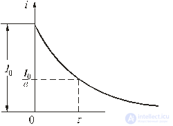
Fig. 5.3
График изменения переходного тока показан на рис. 5.3.
Определим э.д.с. самоиндукции катушки
 t ≥ 0.
В момент коммутации эта э.д.с. равна напряжению на сопротивлении R, а в дальнейшем уменьшается по экспоненциальному закону. На основании изложенного можно сделать следующие выводы.
u L (0 + ) = I 0 R.
 .
.

Fig. 5.4
The transient current in the circuit shown in Fig. 5.4, we will present in the form
i = i y + i of sv .
1. Before switching the current in the coil was not, therefore,
i L (0 - ) = 0.
2. The steady-state component of the current after switching
i y = U / R.
3. The free component of the current for the circuit described by a differential equation of the first order
i St = A e -t / τ = A e pt , p = - R / L.
4. According to the initial conditions, we determine the integration constant A and the free component of the current:
i (0) = i y (0) + i w (0); i (0) = i y (0 + ) + i w (0 - );
or
0 = U / R + A; A = -U / R; i St = -U / R · e -t / τ .
The transient current is obtained as
i = U / R (1 - e -t / τ ).
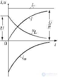
Fig. 5.5
Voltage on the coil
 .
.
Кривые изменения токов i, i y , i св и напряжения на катушке u L показаны на рис. 5.5.
При включении рассматриваемого контура под постоянное напряжение ток в нем нарастает от нуля до установившегося значения. Скорость нарастания тока

изменяется по экспоненте с отрицательным показателем. В момент t = 0 эта скорость максимальна и равна U / L [А/с], со временем она падает практически до нуля, процесс выходит на установившийся режим.
В первый после коммутации момент t = 0 + ток в цепи еще равен нулю, и напряжение на катушке максимально u L = U, далее оно экспоненциально снижается до нуля.
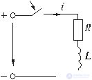
Fig. 5.6
Если напряжение источника цепи (рис. 5.6)
u = U m sin(ωt + ψ),
то установившийся ток
i у = U m / Z sin(ωt + ψ - φ),
Where:  – полное сопротивление цепи;
φ = arctg(ω L/R) - угол сдвига фаз между напряжением и током.
Свободный ток определяется
i св = A e -t/τ .
Суммируя установившуюся и свободную составляющие, получим выражение для переходного тока:
i = i у + i св = U m / Z sin(ωt + ψ - φ) + A e -t/τ .
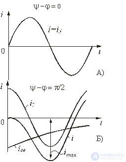
Fig. 5.7
используя независимые начальные условия при t = 0
i(0 - ) = i(0 + ) = 0,
находим постоянную интегрирования:
A = -U m / Z sin(ψ - φ).
Тогда переходный ток:
 .
.
Зависимости переходного тока от времени при различных значениях разностей ψ - φ показаны на рис. 5.7. Их анализ позволяет сделать следующие выводы.
i = i у = I m sin(ωt) = U m / Z sin(ωt).
Рассмотрим переходный процесс при коротком замыкании в цепи с конденсатором и резистором (рис. 5.8), если предварительно конденсатор был заряжен до напряжения
u C (0 + ) = U 0 = Е.

Fig. 5.8
Установившийся ток через конденсатор и установившееся напряжение на конденсаторе равны нулю. Для построения характеристического уравнения запишем по второму закону Кирхгофа уравнение для вновь образованного контура
R i + u C = 0.
При расчете переходных процессов в цепях с конденсатором часто удобнее отыскать сначала не ток, а напряжение на конденсаторе u C , а затем учитывая, что  , найти ток через конденсатор. Поэтому запишем уравнение по второму закону Кирхгофа в виде:
 .
.
The characteristic equation is:
RCp + 1 = 0.
General solution for free voltage component:
u Csb = A e pt = A e -t / τ ,
where: A = U 0 is the integration constant;
p = - 1 / (RC) is the root of the characteristic equation;
τ = RC is the time constant of the circuit.
Given the zero value of the steady-state voltage, we obtain the voltage on the capacitor:
u C = U 0 e -t / τ .
Transient current in the circuit
 .
.
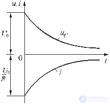
Fig. 5.9
Curves of voltage variation on the capacitor and current in the circuit in time have the form of exponentials (Fig. 5.9).
С энергетической точки зрения переходный процесс характеризуется переходом энергии электрического поля конденсатора в тепловую энергию в резисторе. Следует отметить; что сопротивление резистора влияет не на количество выделенной теплоты, а на начальное значение тока и длительность разряда. В самом деле
 .
.
Из схемы, приведенной на рис. 5.10, следует, что установившаяся составляющая напряжения на конденсаторе u Cу = U, а свободная составляющая, очевидно, равна
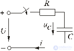
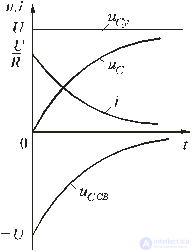
Fig. 5.10
u Cсв = A e -t/τ , τ = RC.
Полагаем, что до замыкания ключа конденсатор не был заряжен (Uс(0 - ) = 0). На основании законов коммутации u C (0 - ) = u C (0 + ) = 0, при t = 0; следовательно:
u C (0) = u Cу (0) + u Cсв (0) или 0 = U + A, откуда А = -U.
Тогда переходное напряжение на конденсаторе
u C = U (1 - e -t/τ ),
а переходный ток в цепи
 .
.
Зависимости напряжений и токов от времени показаны на рис. 5.10. Из них видно, что напряжение на конденсаторе возрастает по экспоненциальному закону от нуля до напряжения источника, а ток уменьшается от начального значения до нуля также по экспоненте. Длительность их изменения определяется постоянной времени τ = RC. Здесь как и в п. 5.5.1 время переходного процесса принимается равным t ≈ (3 ÷ 5)τ.
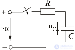
Fig. 5.11
Пусть напряжение источника изменяется по закону
u = U m sin(ωt + ψ).
Установившаяся составляющая напряжения на конденсаторе (см. рис. 5.11) равна:
u Cу = -U m X C / Z sin(ωt + ψ – φ – π / 2).
Where:  - полное сопротивление цепи;
X C = 1 / (ωC) – емкостное сопротивление;
φ = -arctg(X C / R) – угол сдвига фаз между установившимся током в цепи и приложенным синусоидальным напряжением.
Свободная составляющая напряжения на конденсаторе
u Cсв = A e -t/τ , τ = RC.
Переходное напряжение на конденсаторе
 .
.

Fig. 5.12
Полагая, что u C (0 - ) = 0, для постоянной интегрирования получим
 .
.
Окончательно напряжение на конденсаторе можно записать в виде
 .
.
Ток в цепи
 .
.
Зависимости переходного напряжения на конденсаторе от времени при различных значениях разностей ψ - φ показаны на рис. 5.12. Их анализ позволяет сделать следующие выводы.
Если в момент включения мгновенное значение установившегося напряжение на конденсаторе равно нулю (ψ – φ – π / 2 = 0), то и свободная составляющая напряжения равна нулю. В цепи сразу устанавливается режим (рис. 5.12 а).
Если в момент включения мгновенное значение установившегося напряжение на конденсаторе имеет наибольшее значение (ψ – φ – π / 2 = π / 2), то переходное напряжение достигает максимального значения приблизительно через половину периода и может приблизиться к удвоенной амплитуде установившегося напряжения, но не превысит его (рис. 5.12 в).
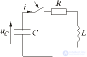
Fig. 5.13
Пусть в цепи, изображенной на рис. 5.13, конденсатор был заряжен до напряжения u C (0 - ) = U 0 . Исследуем процессы в контуре, образованном резистором, конденсатором и катушкой после замыкания в момент t = 0 ключа. Так как источники в цепи отсутствуют, то установившиеся составляющие решений равны нулю. Решение будет состоять из одной свободной составляющей.
По второму закону Кирхгофа t ≥ 0 имеем:
 .
.
Considering that  , получаем дифференциальное уравнение второго порядка для свободной составляющей напряжения
 .
.
Характеристическое уравнение при этом имеет вид:
 .
.
Характер электромагнитных процессов в контуре зависит от соотношения параметров R, L, С, входящих в выражение для корней характеристического уравнения
 .
.
В зависимости от знака подкоренного выражения корни могут быть вещественными или комплексно-сопряженными. Они определяют характер свободных составляющих переходных токов и напряжений.
Рассмотрим процесс разряда конденсатора на резистор R и катушку L. Если параметры контура из резистора, катушки и конденсатора удовлетворяют условию  or
or  , то корни характеристического уравнения контура вещественные, различные, т.е. р 1 ≠ р 2 , и отрицательные. В этом случае напряжение на конденсаторе описывается уравнением
u C = u Cсв = A 1 · e p 1 t + A 2 · e p 2 t ,
где А 1 и А 2 – постоянные интегрирования, определяемые из начальных, условий.
Свободный ток равен
 .
.
Установившиеся составляющие напряжения на конденсаторе и тока равны нулю. Поэтому их переходные значения равны свободным составляющим:
u C = u Cсв ; i = i св .
Определим из начальных условий постоянные интегрирования А 1 и А 2 . При t = 0, u C (0) = U 0 и i(0) = 0. Подставив их в выражения для переходных напряжений и токов при t = 0 имеем
U 0 = A 1 + A 2 ; 0 = A 1 p 1 + A 2 p 2 .
From here
A 1 = U 0 p 2 / (p 2 - p 1 ); A 2 = -U 0 p 1 / (p 2 - p 1 );
С учетом начальных условий запишем
 ;
;  .
.
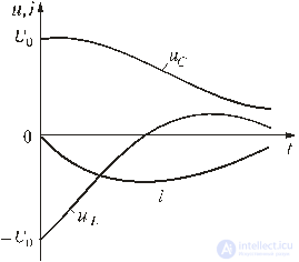
Fig. 5.14
The product of roots according to the theorem of Viet: p 1 p 2 = 1 / (LC), therefore, the current
 .
.
Voltage on the coil
 .
.
The graphs of current and voltage versus time, shown in Fig. 5.14 allow us to speak about aperiodic discharge of a capacitor. A discharge is called aperiodic such that the capacitor discharges all the time, i.e. the function u C (t) is decreasing, and the current i does not change its direction, in our case it is negative. We draw some conclusions.
When the ratio of the parameters of the circuit of the capacitor, coil and resistor
 ,
,
where R КР - critical resistance of resistor R, the roots of the characteristic contour equation are real, equal and negative:
p 1 = p 2 = p = -R / (2L).
The transition process turns out to be aperiodic, but boundary with a collective process. The transient current and transient voltage in this case are:
u C = (A 1 + A 2 t) e pt ;
 .
.
Under initial conditions, u C (0) = U 0 ; i (0) = 0 we find: A 1 = U 0 ; A 2 = -p U 0 . Taking into account the found constants of integration, we obtain the solutions:
u C = U 0 (1 - pt) e pt ;
 ;
;
 .
.
The dependences of i, u C , u L are the same as for aperiodic discharge.
When the ratio of the parameters of the circuit of the capacitor, coil and resistor  , where R КР - critical resistance of the circuit, the roots of the characteristic equation are complex conjugate:
p 1,2 = -α ± jω,
where α = R / (2L) is the attenuation coefficient of the free component;
 - the angular frequency of its own coli *** lower circuit;
T 0 - the period of their own stake *** ***.
Insofar as  then you can enter the notation
 ,
,  ,
,  .
.
The free component of the transient voltage with complex-conjugate roots (see clause 5.2.1)
u Csb = A e −αt sin (ω 0 t +),
For free current component  we have
i St = CA e -αt (-α sin (ω 0 t + ψ) + ω 0 cos (ω 0 t +)).
Taking into account the initial conditions at t = 0, u C = U 0 , i = 0 from the last two equations, we find the integration constants:
U 0 = A sin ψ; 0 = CA (-α sin ψ + ω 0 cos ψ).
and further
 .
.
We write the transient voltage and current:
u C = U Cm e −αt sin (ω 0 t +);
i = -I m e -αt sin (ω 0 t + π);
u L = U Lm e −αt sin (ω 0 t - ψ),
Where  ;
;  .
.

Fig. 5.15
The dependences of transient voltages and currents u C , i are shown in fig. 5.15. They are damped sinusoids. The decay rate of a cole *** is estimated by decrement of a cole *** un. The decrement of a *** colony is a constant that depends on the parameters R, L, C and is equal to the ratio of the amplitudes of the transient parameters lagging behind each other for a period of *** *** T 0 , for example:
 .
.
Often they use the logarithmic decrement of a *** ring
 .
.
In the limiting case of a purely conservative system (R = 0) Δ = 1, the number of *** in the parallel-connected capacitor and coil are non-damping. The period of these *** is given by the Thompson formula  , and the frequency of continuous coke *** ***
  .
.
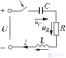
Fig. 5.16
Consider the electromagnetic processes that occur after the key is closed in the circuit shown in Fig. 5.16 on the assumption that the capacitor was not precharged, i.e. u C (0 - ) = 0. The characteristic equation and the form of its roots will be the same as in the chain discussed in Section 5.6.
Between the discharge of a capacitor to a resistor with a coil and the inclusion of a constant voltage circuit (see. Fig. 5.16) there is an analogy. Just as with the discharge of a capacitor, the steady-state current component is zero. The settled voltage on the capacitor u Cu = U. Therefore, the initial value of the free component of the voltage on the capacitor
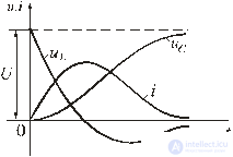
Fig. 5.17
u Csb (0 + ) = u C (0 + ) - u Cy (0 - )
equals u Csb (0 + ) = -U. That is, the signs of the integration constants А 1 and А 2, in contrast to the case considered in Section 5.6, are reversed. In this case, the transition voltage on the capacitor, the current and voltage on the coil are determined by the formulas:
 ;
;
 ;
;  .
.
Curves u C (t), u L (t) and i (t) are shown in fig. 5.17.
The inclusion of the considered circuit at a constant voltage may be accompanied by a vibrant transient process. At the same time, unlike the process of capacitor discharge (see Section 5.6), the sign of the initial value of the transient voltage, and therefore the coefficient A, changes to the opposite. Transient voltage and current will look like:
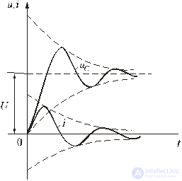
Fig. 5.18
 ;
;
 ;
;
 .
.
The curves u C (t) and i (t) are shown in Fig. 5.18. The current curve displays the damped collisions of *** with respect to the zero value, and the voltage across the capacitor with respect to the steady-state value. It should be noted that during the transition process of the circuit, part of the source energy is transferred to heat, and the other part is stored in the electric field of the capacitor in the form:

those.  .
.

Comments
To leave a comment
Electrical Engineering, Circuit design
Terms: Electrical Engineering, Circuit design